Wireless power transmission system
a power transmission system and wireless technology, applied in the direction of manipulators, electrical appliances, manufacturing tools, etc., can solve the problems of inability to follow a sudden change in load voltage, undesirable time-consuming,
- Summary
- Abstract
- Description
- Claims
- Application Information
AI Technical Summary
Benefits of technology
Problems solved by technology
Method used
Image

Examples
first embodiment
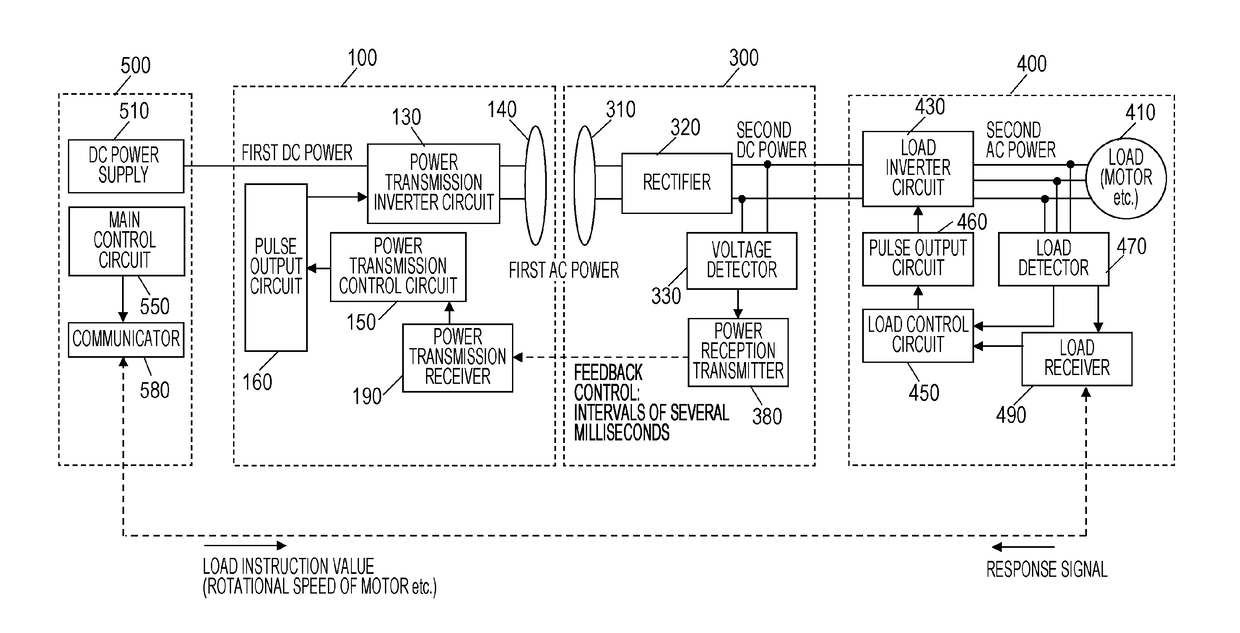
[0104]FIG. 6 is a block diagram illustrating the configuration of a wireless power transmission system according to a first embodiment of the present disclosure. A physical configuration of the wireless power transmission system according to the present embodiment is the same as that in a comparison example illustrated in FIG. 4, but the operation of a main control circuit 550 in a power control apparatus 500 is different. In the present embodiment, when transmitting a load instruction value to the load driving apparatus 400, the main control circuit 550 sets a control parameter of a power transmission inverter circuit 130 to an appropriate value according to the load instruction value and transmits the control parameter to a power transmission apparatus 100. The power transmission apparatus 100 drives the power transmission inverter circuit 130 using the control parameter according to the load instruction value. As a result, a desired operation state can be achieved in a short period
second embodiment
[0160]Next, a wireless power transmission system according to a second embodiment of the present disclosure will be described. The wireless power transmission system in the present embodiment is different from the wireless power transmission system in the first embodiment in that one or more relay apparatuses 200 are provided between the power transmission apparatus 100 and the power reception apparatus 300.
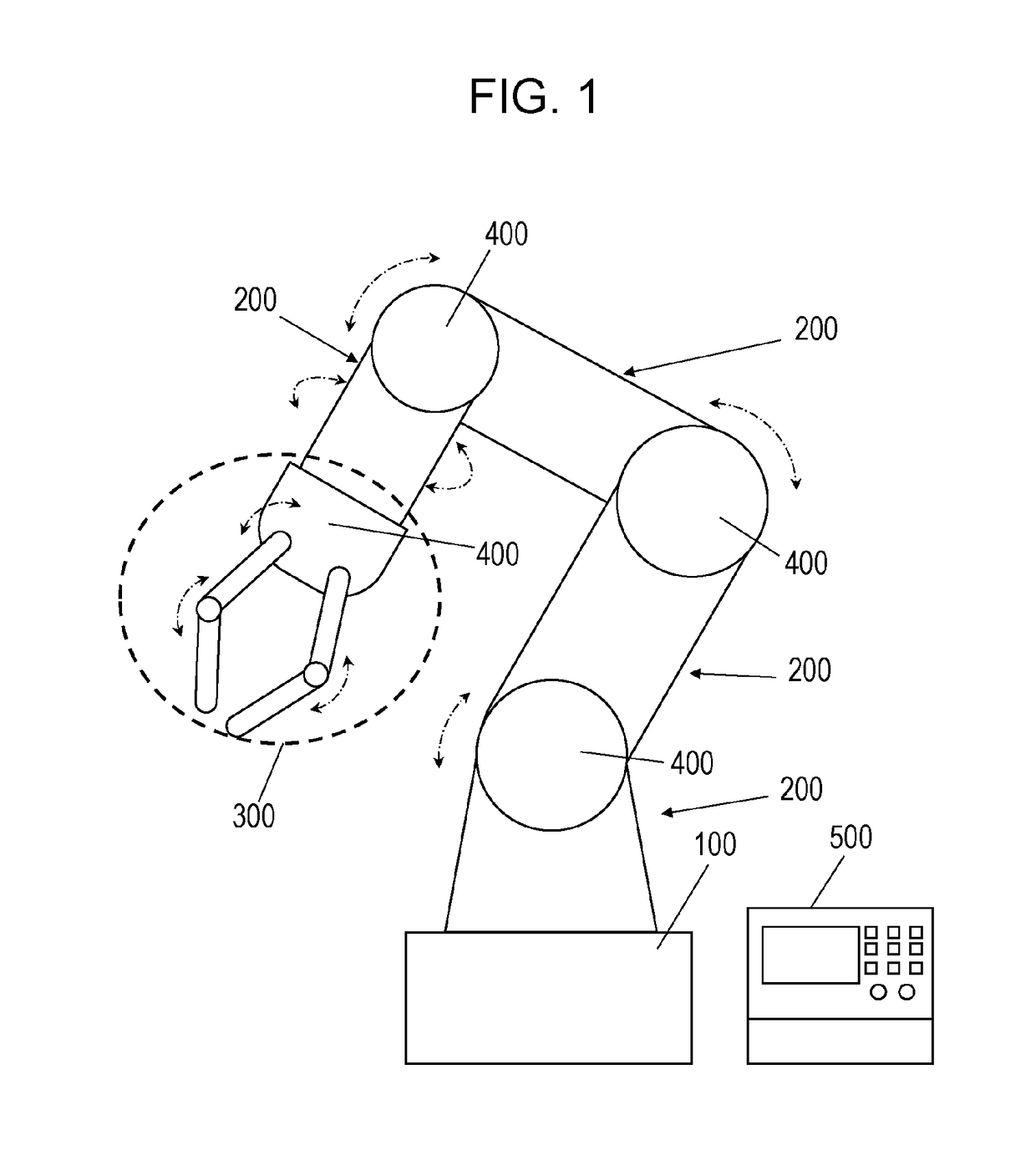
[0161]FIG. 25 is a diagram illustrating a schematic configuration of the wireless power transmission system according to the second embodiment. FIG. 25 illustrates an example of a configuration in which N (N is an integer equal to or larger than 2) relay apparatuses 200 are provided between the power transmission apparatus 100 and the power reception apparatus 300. If the wireless power transmission system in the present disclosure is applied to a device including a large number of movable units, such as the robot arm illustrated in FIG. 1, the configuration illustrated in FIG. 25 i
PUM
 Abstract
Description
Claims
Application Information
 - R&D Engineer
- R&D Manager
- IP Professional
- Industry Leading Data Capabilities
- Powerful AI technology
- Patent DNA Extraction
Browse by: Latest US Patents, China's latest patents, Technical Efficacy Thesaurus, Application Domain, Technology Topic.
© 2024 PatSnap. All rights reserved.Legal|Privacy policy|Modern Slavery Act Transparency Statement|Sitemap