Liquid consuming apparatus and ink-jet printer

Active Publication Date: 2017-05-04
BROTHER KOGYO KK
View PDF1 Cites 9 Cited by
  • Summary
  • Abstract
  • Description
  • Claims
  • Application Information

AI Technical Summary

Benefits of technology

The invention relates to an apparatus that allows liquids to flow freely from one container to another without any interruptions or blocking up. This makes it easier for people who work with these containers to use them effectively.

Problems solved by technology

The technical problem addressed by this patent is how to efficiently use space within printers while ensuring efficient cleaning and maintenance operations for their components.

Method used


Image

  • Liquid consuming apparatus and ink-jet printer
  • Liquid consuming apparatus and ink-jet printer
  • Liquid consuming apparatus and ink-jet printer

Examples


first modification

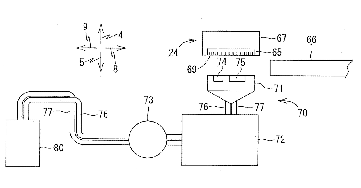
[0077]The waste ink sucked from the recording head 65 by the purging mechanism 70 finally arrives at the above-described second waste-liquid tank 110. Thus, a sensor for detecting the ink may be provided on the second waste-liquid tank 110 at a position at which the waste ink finally arrives.

[0078]As illustrated in FIGS. 14-16, for example, a sensor 132 is disposed on a front left portion of the second body 112 of the second waste-liquid tank 110 at a position inside the side wall 117. The front left portion of the second body 112 inside the side wall 117 is a most downstream portion of a path of the waste ink which is defined by the ribs 126 provided on the second body 112. A well-known sensor may be employed for the sensor 132 as long as the sensor can electrically detect the ink.

[0079]As illustrated in FIG. 16, a rib 133 is provided in the inner space of the second body 112 at a rear of the front left portion at which the sensor 132 is provided. The rib 133 protrudes in the up direc

second modification

[0082]As illustrated in FIG. 17, the MFP 10 may be configured such that a supply tray 143 is selectively mounted in a space defined under the supply tray 20. This configuration enables the supply trays 20, 143 to accommodate sheets of different types and sizes and the image recorder 24 to perform image recording on the sheets without replacement of the sheets.

[0083]As described above, the supply tray 20 is mounted in the space 34 of the lower cover 30 and supported by the lower cover 30. The supply tray 20 is one example of a first sheet tray, and the lower cover 30 is one example of a third housing. As illustrated in FIG. 17, a housing 40 constituting portions of the front, side, and rear surfaces of the MFP 10 is assembled to the lower cover 30 of the printer housing 11, and the supply tray 143 is supported by the housing 40. The housing 40 is one example of a fourth housing, and the supply tray 143 is one example of a second sheet tray. The supply tray 143 is similar in construction


PUM


Abstract

A liquid consuming apparatus includes: a liquid consumer; a liquid receiver; a first waste-liquid storage including (i) a first housing connected to the liquid receiver to allow liquid communication between the first housing and the liquid receiver, and (ii) a first liquid absorber disposed in the first housing; and a second waste-liquid storage including (a) a second housing connected to the first waste-liquid storage to allow liquid communication between the second housing and the first waste-liquid storage, and (b) a second liquid absorber disposed in the second housing. The first housing has a first opening that opens toward the second housing. The second housing has a second opening that opens toward the first housing. The first liquid absorber protrudes from the first opening to an outside of the first housing. The second liquid absorber is in contact with the first liquid absorber protruding from the first opening.

Description


Claims


Application Information

Patent Timeline
Owner BROTHER KOGYO KK
Why Eureka
Try Eureka