Method for maintenance of liquid discharge head and liquid discharge apparatus

Active Publication Date: 2017-09-14
FUJIFILM CORP
View PDF1 Cites 3 Cited by
  • Summary
  • Abstract
  • Description
  • Claims
  • Application Information

AI Technical Summary

Benefits of technology

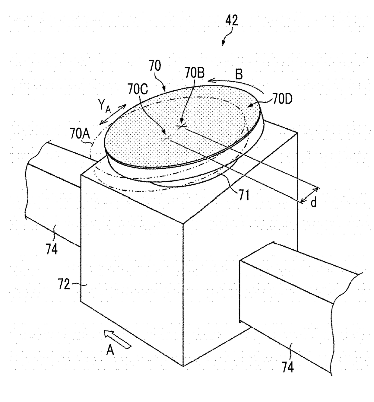
[0055]According to the invention, the nozzles can be wiped in multiple directions since the wiping surface is eccentrically rotated. Further, since the wiping surface including raised irregularities is used, adhering materials present in the nozzles can be removed by the raised irregularities thrust into the nozzles. Since the purge proce

Problems solved by technology

However, an effect of recovering the discharge performance of the liquid discharge head has been insufficient.
The wiping device disclosed in JP2012-51184A and the wiping device disclosed in JP2013-71360A can remove the materials adhering to the peripheries of the nozzles and materials adhering to the liquid discharge surface, but it is difficult for the wiping devices to remove the adher

Method used


Image

  • Method for maintenance of liquid discharge head and liquid discharge apparatus
  • Method for maintenance of liquid discharge head and liquid discharge apparatus
  • Method for maintenance of liquid discharge head and liquid discharge apparatus

Examples


modification examples

[0414]Next, modification examples of this embodiment will be described.

first modification example

of Wiping Processing

[0415]FIG. 21A is a view illustrating wiping processing for a forward path according to a first modification example. Further, FIG. 21B is a view illustrating wiping processing for a backward path according to the first modification example. Only a part of the liquid discharge head 16 and only a part of a wiping member 70 are shown in FIGS. 21A and 21B.

[0416]In the wiping processing shown in FIGS. 21A and 21B, the wiping member 70 is made to reciprocate over the entire length of the liquid discharge head 16 in the longitudinal direction of the liquid discharge head 16 to wipe the entire liquid discharge surface 30 two times.

[0417]Since the number of times of contact between the wiping member 70 and the liquid discharge surface 30, the nozzles 280 shown in FIG. 5, and the inside of the nozzles 280 is further increased in the wiping processing shown in FIGS. 21A and 21B, adhering materials present on the liquid discharge surface 30, the nozzles 280, and on the inside

second modification example

[0421]FIG. 22A is a view illustrating wiping processing for a forward path according to a second modification example. FIG. 22B is a view illustrating wiping processing for a backward path according to the second modification example.

[0422]In the wiping processing shown in FIGS. 22A and 22B, a wiping member 70E, which has a diameter or a total length shorter than the entire length of the liquid discharge head 16 in a lateral direction YA, is used and the wiping member 70E is made to reciprocate at least one time over the entire length of the liquid discharge head 16 in the longitudinal direction of the liquid discharge head 16 to wipe the entire liquid discharge surface 30 one times.

[0423]In the wiping processing shown in FIGS. 22A and 22B, the wiping member 70E is made smaller than the wiping member 70 shown in FIG. 8 and the like and the effects of the wiping processing are maintained. Reference numeral 90C shown in FIG. 22A denotes the trajectory of an arbitrary point on a wiping su


PUM


Abstract

The method includes: a wiping processing step of performing wiping processing on a liquid discharge surface by eccentrically rotating a wiping surface of a wiping member, including raised irregularities on the wiping surface thereof, in a plane parallel to the liquid discharge surface of a liquid discharge head and moving the wiping member in a first direction in a state in which the wiping surface is in contact with the liquid discharge surface; and a post-wiping processing purge processing step of performing post-wiping processing purge processing after the wiping processing step. An eccentric parameter as a value obtained by dividing an eccentric distance of the wiping surface by an interval between the nozzles in a second direction orthogonal to the first direction, is set to 10 or more in the wiping processing step.

Description


Claims


Application Information

Patent Timeline
Owner FUJIFILM CORP
Why Eureka
Try Eureka