Vehicle control system for internal combustion engine

a technology of control system and internal combustion engine, which is applied in the direction of electric control, ignition automatic control, machines/engines, etc., can solve the problems of reducing the wall temperature of the combustion chamber and deteriorating overall exhaust performance, so as to reduce the number of exhaust particles and reduce the adhesion of fuel to the wall surface of the combustion chamber

Active Publication Date: 2017-12-07
NISSAN MOTOR CO LTD
View PDF0 Cites 1 Cited by
  • Summary
  • Abstract
  • Description
  • Claims
  • Application Information

AI Technical Summary

Benefits of technology

The present invention allows for better control over the temperature at which the engine starts up after being started with lean spikes. This reduces the amount of harmful emissions released from the engine compared to traditional methods that require longer periods before reaching full performance.

Problems solved by technology

The technical problem addressed in this patent is how to prevent condensing or sticking of particulate matter (PM) onto the walls of the combustion chamber during the fuel cutting-off process while also improving the efficiency of the exhaust treatment system for vehicles equipped with these systems.

Method used


Image

  • Vehicle control system for internal combustion engine
  • Vehicle control system for internal combustion engine
  • Vehicle control system for internal combustion engine

Examples


Embodiment Construction

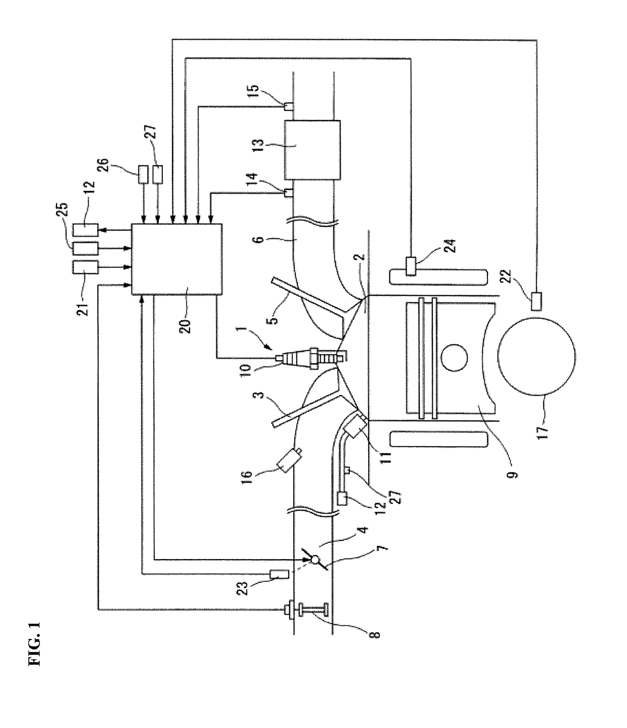
[0015]Below, embodiments of the present invention are described in detail with reference to the accompanying drawings. In embodiments of the invention, numerous specific details are set forth in order to provide a more thorough understanding of the invention. However, it will be apparent to one of ordinary skill in the art that the invention may be practiced without these specific details. In other instances, well-known features have not been described in detail to avoid obscuring the invention. FIG. 1 shows a schematic configuration of an internal combustion engine 1 according to one or more embodiments of the present invention. Note that the internal combustion engine 1 uses gasoline as fuel, for example.

[0016]A combustion chamber 2 of the internal combustion engine 1 is connected to an intake passage 4 with an intake valve 3 interposed. Further, the combustion chamber 2 is connected to an exhaust passage 6 with an exhaust valve 5 interposed.

[0017]In the intake passage 4, a throttle


PUM


Abstract

A vehicle control system for an internal combustion engine having a fuel injection valve for injecting fuel directly into a combustion chamber includes a controller configured to perform a fuel cut-off when a predetermined fuel cut-off condition is met during travel of the vehicle to thereby stop fuel injection from the fuel injection valve. The controller is configured to resume the fuel injection from the fuel injection valve when a predetermined fuel cut-off recovery condition is met during the fuel cut-off. The controller is configured, upon elapse of a predetermined time that is required for a wall temperature of the combustion chamber to rise after resuming the fuel injection from the fuel injection valve, to perform a rich spike that temporarily increases the fuel injection amount from the fuel injection valve.

Description


Claims


Application Information

Patent Timeline
Owner NISSAN MOTOR CO LTD
Why Eureka
Try Eureka