Hook device and hook assembly including the hook device

a technology of a hook device and a hook assembly, which is applied in the direction of application, fastening means, picture frames, etc., can solve the problems of insufficient strength, difficult to be removed, and mark will be left, and achieve the effects of convenient use and removal, convenient fixing or removal from a flat surface, and convenient us

Inactive Publication Date: 2018-03-22
PANTENE INDAL
View PDF6 Cites 0 Cited by
  • Summary
  • Abstract
  • Description
  • Claims
  • Application Information

AI Technical Summary

Benefits of technology

This patented technology provides a hook device used to apply pressure sensitive adhesives onto surfaces quickly without leaving any residue behind after they are applied. It also allows for easy removal of the adherend's back while still being able to maintain its bond strength when exposed to high temperatures during application.

Problems solved by technology

The technical problem addressed in this patent text relates to improving the design of hook products made from materials like wood plank surfaces and metal planks, while maintaining their strength and ease of removal.

Method used


Image

  • Hook device and hook assembly including the hook device
  • Hook device and hook assembly including the hook device
  • Hook device and hook assembly including the hook device

Examples


Embodiment Construction

[0028]For understanding the objective, the technical content and the advantages of the present invention more sufficiently, some embodiments of the present invention will be described as follows, by way of example only, with reference to the accompanying drawings. The embodiments disclosed below are not intended to be exhaustive or to limit the invention to the precise forms disclosed in the following detailed description.

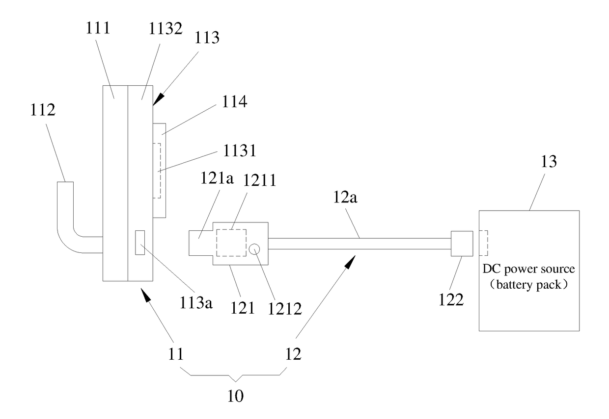
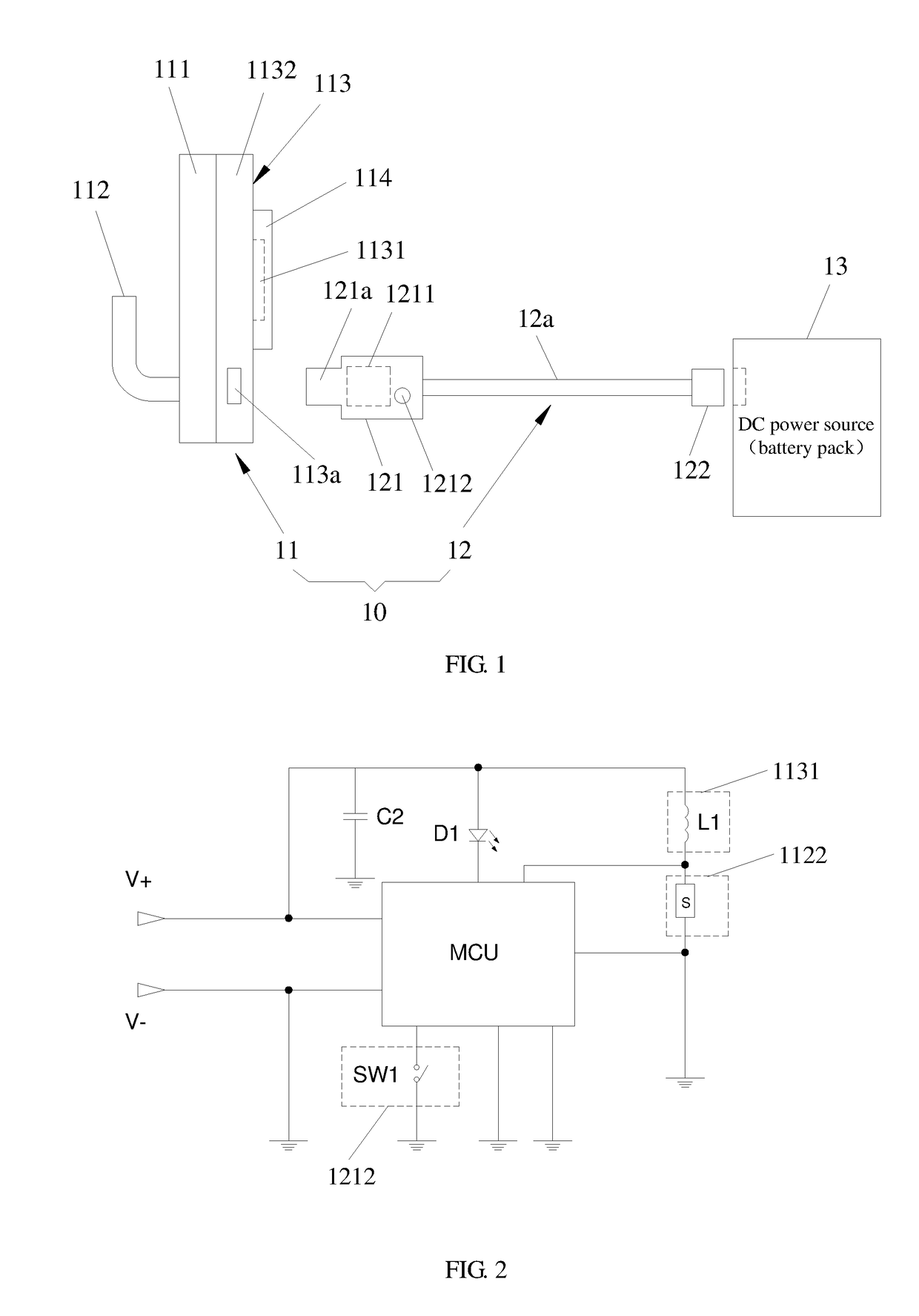
[0029]FIG. 1 illustrates a first embodiment of the hook assembly according to the present invention. FIG. 2 illustrates a circuit schematic diagram of the hook assembly according to the present invention.

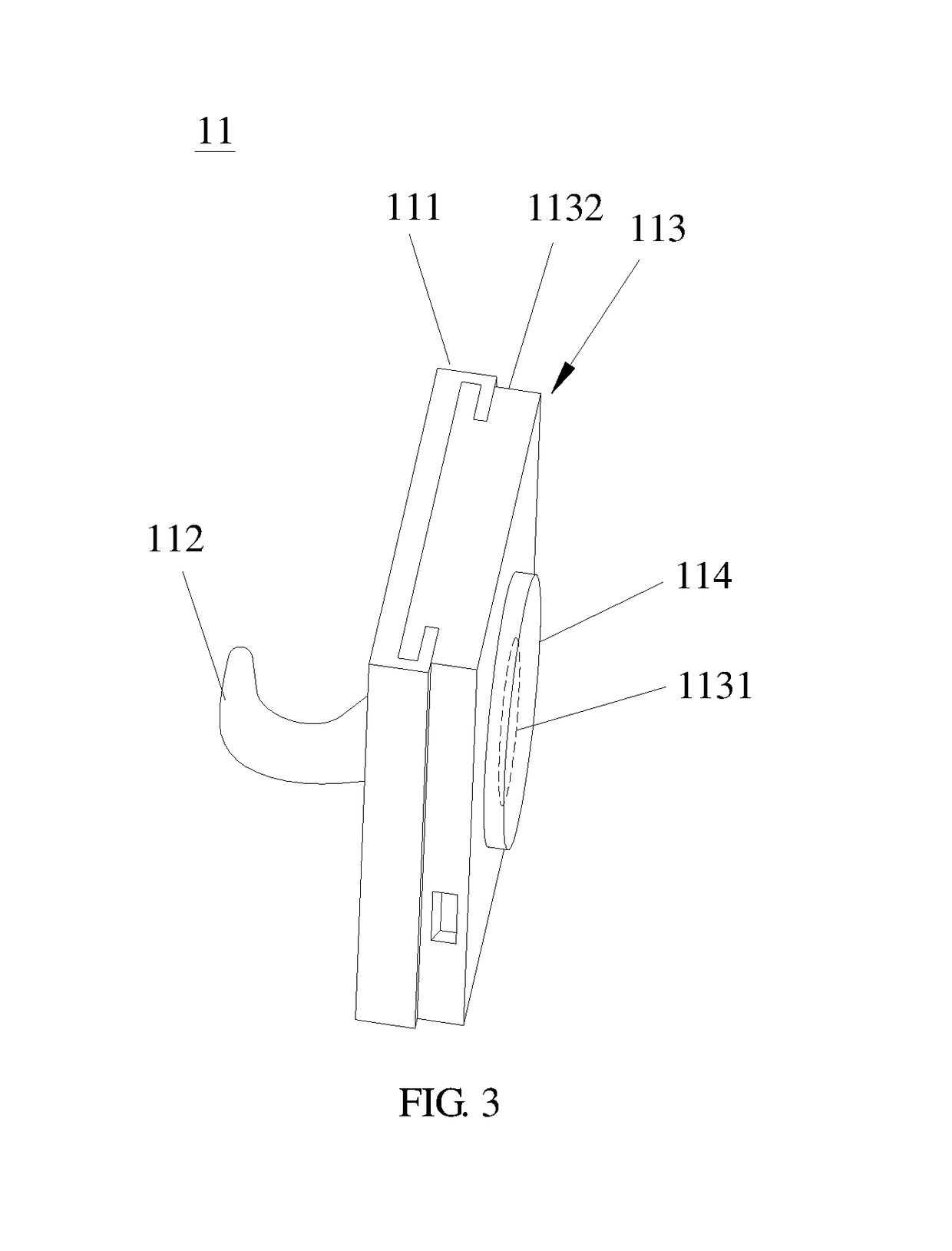
[0030]At first, referring to FIG. 1, the hook assembly 10 according to the first embodiment includes a hook device 11 and a connecting cable 12 cooperated with the hook device 11 for use. The hook device 11 includes a hook base 111, a front side of which is provided with a hook tip 112 and a rear side of which is provide with a heating module 113 and a hot melt adhesi


PUM


Abstract

Disclosed is a hook device, which includes a hook base, a hook provided on a front side of the hook base, and a heating module and a hot melt adhesive layer both provided on a rear side of the hook base. The heating module includes a heating element which contacts with the hot melt adhesive layer. In addition, the present invention further discloses a hook assembly, which includes the above hook device and further includes a connecting cable provided for connecting a power source. The connecting cable is provided with a control circuit to control a heating time of the hot melt adhesive layer. When the power source is switched on, by means of the heating element controlled by the control circuit, the hot melt adhesive layer will be heated and then melted so that it is easy to be fixed to or removed from a flat surface.

Description


Claims


Application Information

Patent Timeline
Owner PANTENE INDAL
Why Eureka
Try Eureka