System and method for product data management and 3D model visualization of electrical wiring design and specifications

Active Publication Date: 2018-04-12
SN DETUDE & DE CONSTR DE MOTEURS DAVIATION S N E C M A
View PDF2 Cites 6 Cited by
  • Summary
  • Abstract
  • Description
  • Claims
  • Application Information

AI Technical Summary

Benefits of technology

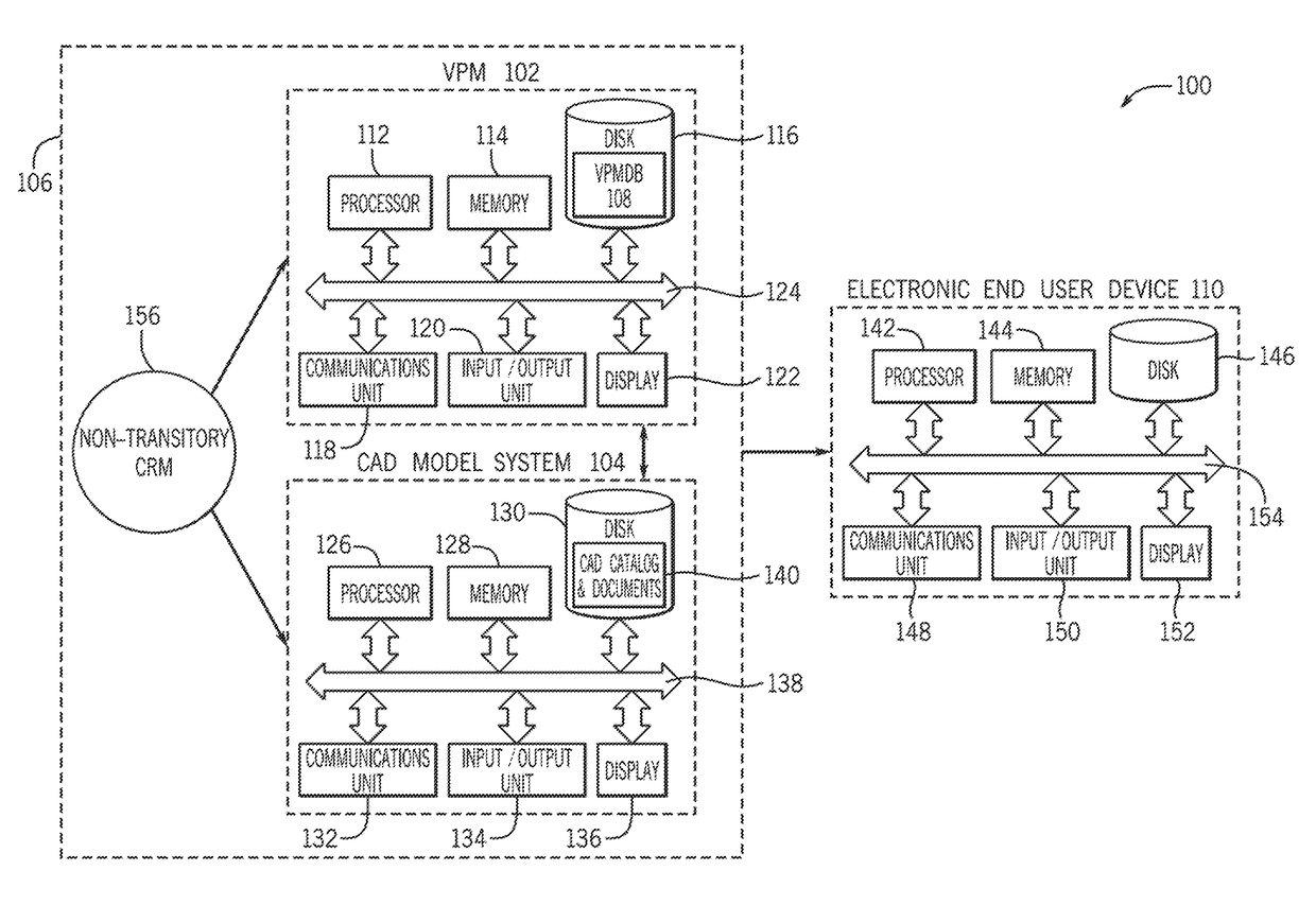
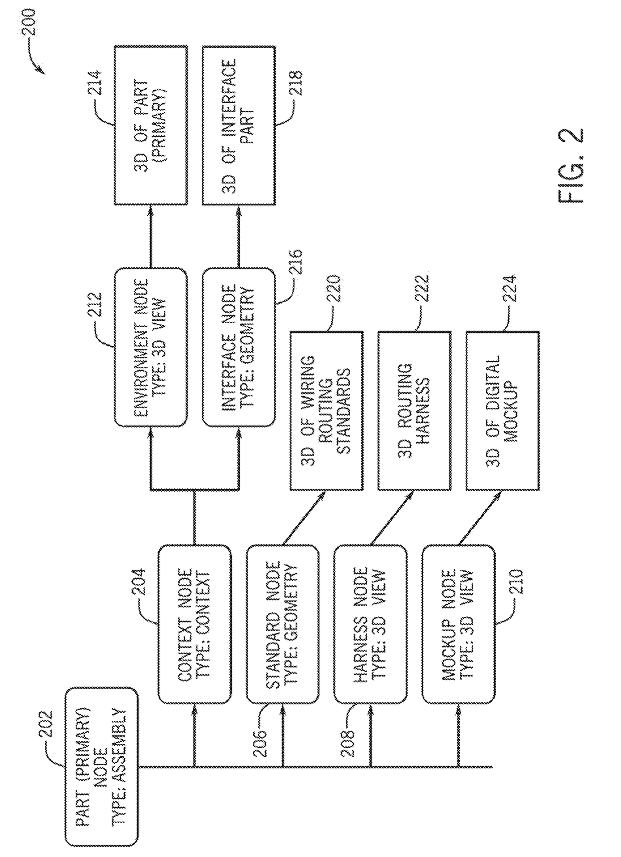
[0002]According to one aspect, a computer-implemented method for generating a three-dimensional (3D) computer model of an assembly including wiring routing, includes, creating a part data structure defining a part in a virtual product management system and storing the part data structure in a virtual product management database. The part data structure includes a plurality of nodes defining at least 3D part design data, 3D routing design data and wiring routing annotation data of the part. The method includes importing at least the 3D part design data, the 3D wiring routing design data and the wiring routing annotation data to the part data structure from a computer-aided design (CAD) model system. The CAD model system is operably connected for computer communication to the virtual product management system and the virtual product management database. Further, the method includes generating a 3D computer model of the assembly including one or more parts based on one or more part data structures stored in the virtual product management database. The 3D computer model of the assembly combines the 3D part design data, the 3D wiring routing design data and the wiring routing annotation data. The method also includes transmitting the 3D computer model of the assembly to an electronic end user device.
[0003]According to another aspect, a system for generating a three-dimensional (3D) computer model of an assembly including wiring routing, includes a virtual product management system operably connected for computer communication to a virtual product management database and a computer-aided design (CAD) model system. The CAD model system is operably connected for computer communication to the virtual product management system and the virtual product management database. An electronic end user device is operably connected for computer communication to the virtual product management system. Further, a processor is operably connected for computer communication to the virtual product management system, the virtual product management database, the CAD model system, and the electronic end user device. The processor is configured to create a part data structure

Problems solved by technology

This information can be distributed between multiple storage systems and product data mana

Method used


Image

  • System and method for product data management and 3D model visualization of electrical wiring design and specifications
  • System and method for product data management and 3D model visualization of electrical wiring design and specifications
  • System and method for product data management and 3D model visualization of electrical wiring design and specifications

Examples


Embodiment Construction

[0020]The following includes definitions of selected terms employed herein. The definitions include various examples and / or forms of components that fall within the scope of a term and that can be used for implementation. The examples are not intended to be limiting. Further, the components discussed herein, can be combined, omitted or organized with other components or into organized into different architectures.

[0021]A “bus”, as used herein, refers to an interconnected architecture that is operably connected to other computer components inside a computer or between computers. The bus can transfer data between the computer components. The bus can be a memory bus, a memory controller, a peripheral bus, an external bus, a crossbar switch, and / or a local bus, among others. The bus can also be a vehicle bus that interconnects components inside a vehicle using protocols such as Media Oriented Systems Transport (MOST), Controller Area network (CAN), Local Interconnect Network (LIN), amo


PUM


Abstract

A method for generating a three-dimensional (3D) computer model of an assembly that includes wiring routing, which includes creating a part data structure that defines a part in a virtual product management system. The part data structure includes a plurality of nodes that define at least 3D part design data, 3D wiring routing design data and wiring routing annotation data of the part. The method includes importing at least the 3D part design data, the 3D wiring routing design data and the wiring routing annotation data to the part data structure from a computer-aided design (CAD) model system and generating a 3D computer model of the assembly. The method also includes transmitting the 3D computer model of the assembly to an electronic end user device.

Description


Claims


Application Information

Patent Timeline
Owner SN DETUDE & DE CONSTR DE MOTEURS DAVIATION S N E C M A
Why Eureka
Try Eureka