Additive manufacturing arrangement with shared radiation source

a technology of additive manufacturing and radiation source, applied in the field of additive manufacturing, can solve the problems of reducing yield, affecting compliance, increasing energy deposition artifacts, etc., and achieves the effects of reducing costs, high and consistent yield, and reducing varian

Inactive Publication Date: 2018-06-14
ADDIFAB APS
View PDF2 Cites 2 Cited by
  • Summary
  • Abstract
  • Description
  • Claims
  • Application Information

AI Technical Summary

Benefits of technology

The technical effect of this patented method described for improving production efficiency while reducing cost-effectiveness involves creation of different parts from one machine at once without compromising their quality level. This reduces variations between machines' results and saves money on purchasing equipment needed during operation.

Problems solved by technology

The technical problem addressed in this patents relates to improves the efficiency and accuracy of producing complex structures made up of different materials without sacrificial effects caused by overlapping layers. Existing methods involve adding extra power during fabrication, but they can lead to decreasing yields due to increases in stress levels and reduced productivity rates. There also exist techniques called multi-beam methodologies, which aim towards achieving greater flexibility in terms of design freedom compared to current methods like monoenergeurics.

Method used


Image

  • Additive manufacturing arrangement with shared radiation source
  • Additive manufacturing arrangement with shared radiation source
  • Additive manufacturing arrangement with shared radiation source

Examples


Embodiment Construction

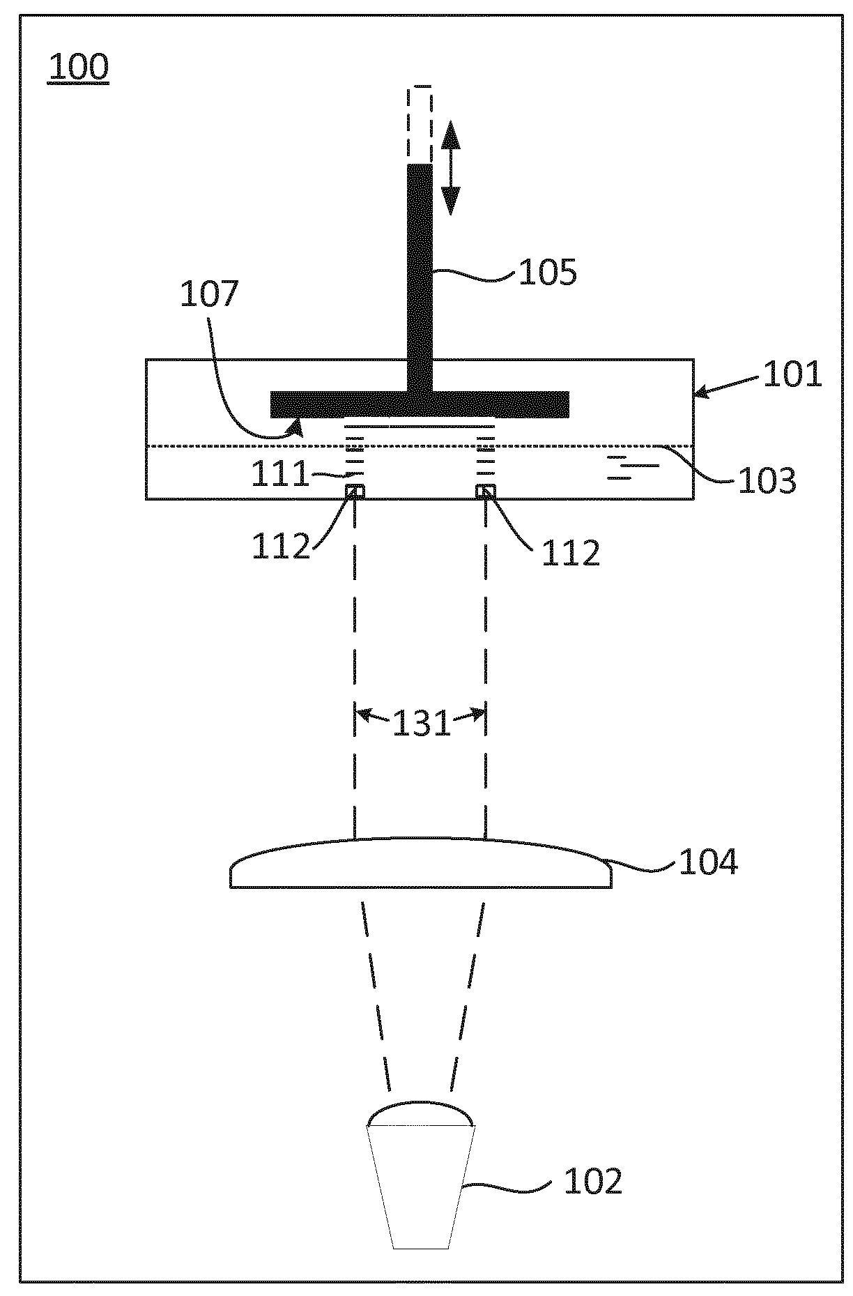
[0042]FIG. 1 generically illustrates a bottom-projection type of additive manufacturing apparatus 100. It comprises a vat 101 or other suitable container for holding a radiation-curable liquid 103 (indicated by its surface); a movable platform 105 having a build surface 107 that can be moved relative to the vat e.g. as indicated by the double arrow; and a radiation source 102 for providing hardening radiation 131 for selectively solidifying radiation-curable liquid in the vat. A lens system 104 focuses the radiation onto the radiation-curable liquid. The radiation source can provide radiation in a pattern corresponding to a layer to be formed. Element 111 illustrates already formed layers. Element 112 illustrates a newly formed layer, the shape of which is defined by the pattern provided by the radiation source. The radiation-curable liquid 103 and layers 111 and 112 are not part of the apparatus but are included to illustrate how a product is manufactured during an additive manufactur


PUM

PropertyMeasurementUnit
Wavelengthaaaaaaaaaa

Abstract

The present invention provides an additive manufacturing arrangement comprising at least a first and a second additive manufacturing apparatus, each additive manufacturing apparatus comprising: a container for holding a radiation-curable liquid, a build platform having a build surface for holding a product to be manufactured during a manufacturing process, the build platform being movable relative to the container in a predetermined direction, a local radiation source configured to provide hardening radiation for selectively hardening radiation-curable liquid in the container to form the product; and the arrangement is characterized in that the arrangement comprises a first central radiation source configured to provide hardening radiation for selectively hardening radiation-curable liquid in the first and second container of the respective first and second additive manufacturing apparatus, and each local radiation source comprises a radiation input configured to receive hardening radiation from the first central radiation source and to emit at least part of said hardening radiation to selectively harden radiation-curable liquid in the corresponding container, and there is a first radiation splitter for splitting radiation from the first central radiation source into at least a first part and a second part, wherein the additive manufacturing arrangement is arranged to provide the first part to the radiation input of the first additive manufacturing apparatus and arranged to provide the second part to the radiation input of the second additive manufacturing apparatus.

Description


Claims


Application Information

Patent Timeline
Owner ADDIFAB APS
Why Eureka
Try Eureka