Production method for a component having integrated channels and component

a production method and integrated channel technology, applied in the direction of turbines, machines/engines, manufacturing tools, etc., can solve the problems of low productivity, inadequate product benefits, and currently only limited options for combining additive manufacturing processes with established manufacturing techniques

Pending Publication Date: 2022-04-07
SIEMENS ENERGY GLOBAL GMBH & CO KG
View PDF0 Cites 0 Cited by
  • Summary
  • Abstract
  • Description
  • Claims
  • Application Information

AI Technical Summary

Benefits of technology

This patent describes how an opening can be used to control the flow of fluids within a channel that has two regions: one where there are changes in its flow direction, while another area where there're no changes. These areas have different sizes and shapes, allowing for more precise control over the flow of fluids.

Problems solved by technology

The technical problem addressed in this patent is how to combine different types of additive manufacture methods (such as laser sintering) together while ensuring economic efficiency and effective use of resources.

Method used


Image

  • Production method for a component having integrated channels and component
  • Production method for a component having integrated channels and component

Examples


Embodiment Construction

[0025]Identical reference designations have the same meaning in the various figures.

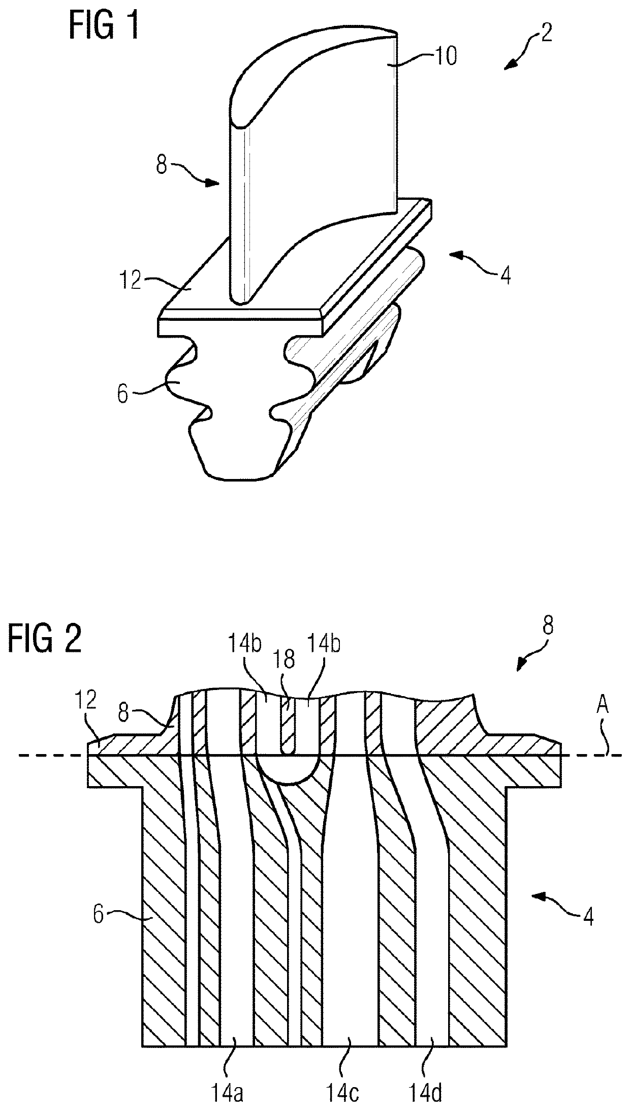
[0026]FIG. 1 shows a turbine blade 2, here a guide blade, which is of two-part construction.

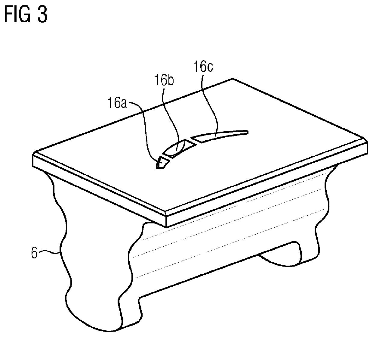
[0027]A first region 4 of the turbine blade 2 is constructed as a cast part and substantially comprises a blade root 6 of the turbine blade 2. This first region 4 is produced in series by means of a process for casting with lost models, in particular by means of precision casting. In precision casting, a wax model in the form of the workpiece to be produced is made for each cast part. In this case, the production of the cast part 4 has been significantly simplified in that the blade root 6 does not have any undercuts. Thus, no ceramic cores are used in the production of the blade root 6.

[0028]A second region 8 of the turbine blade 2 is produced by means of a generative manufacturing process and comprises a blade airfoil 10 and a small part 12 of the blade root 6, said small part adjoining the blade airfoil 10. A


PUM


Abstract

A production method for a component having integrated channels for internal fluid guidance, having a first region, which is connected to a second region, and wherein the channels extend both through the first region and through the second region. The geometry of the component is modified to the technological characteristics of both production methods. The first region is produced by a method for casting using lost models without undercuts, and proceeding from the first region, the second region is built up using an additive manufacturing method.

Description


Claims


Application Information

Patent Timeline
Owner SIEMENS ENERGY GLOBAL GMBH & CO KG
Why Eureka
Try Eureka