Base unit, motor, and air blowing device

a technology of air blowing device and base unit, which is applied in the direction of machines/engines, mechanical equipment, liquid fuel engines, etc., can solve the problems of decreasing and achieve the effect of reducing the reliability of the base uni

Inactive Publication Date: 2018-09-06
NIPPON DENSAN CORP
View PDF0 Cites 2 Cited by
  • Summary
  • Abstract
  • Description
  • Claims
  • Application Information

AI Technical Summary

Benefits of technology

In this patented design for a base machine (BM), when multiple cords pass through it's housing, they can move sideways within its structure due to gravity forces caused by the weight on top. This movement makes sure all these cords stay securely attached during use but also causes them to shift laterally along their length if needed again. To solve this issue, some designs have included guides around the edges where cords enter into holes made in the walls inside the BSM itself. These guiding features help keep cords aligned properly while still being secured tight against the surrounding material.

Problems solved by technology

This patented describes an electronics device called this type of equipment used for computers (PC). It consists of one basic component - it's made from plastic material like PVC) which has several columns of small metal pins on its back surface. These tiny pins help connect different components together inside the PC case.

Method used


Image

  • Base unit, motor, and air blowing device
  • Base unit, motor, and air blowing device
  • Base unit, motor, and air blowing device

Examples


Embodiment Construction

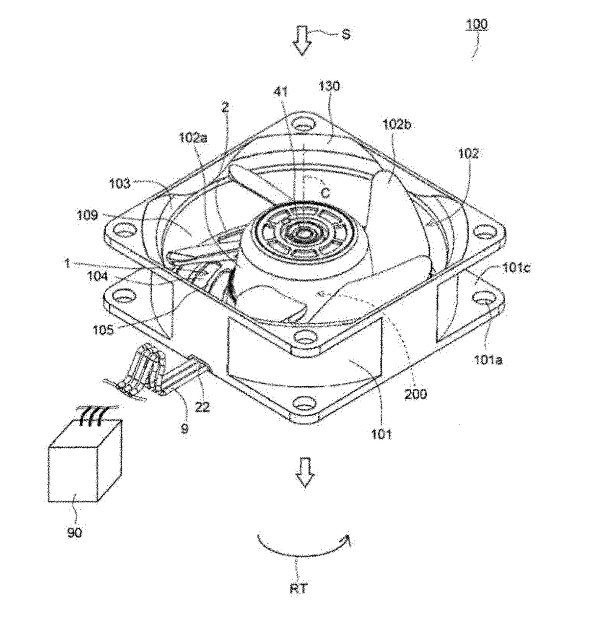
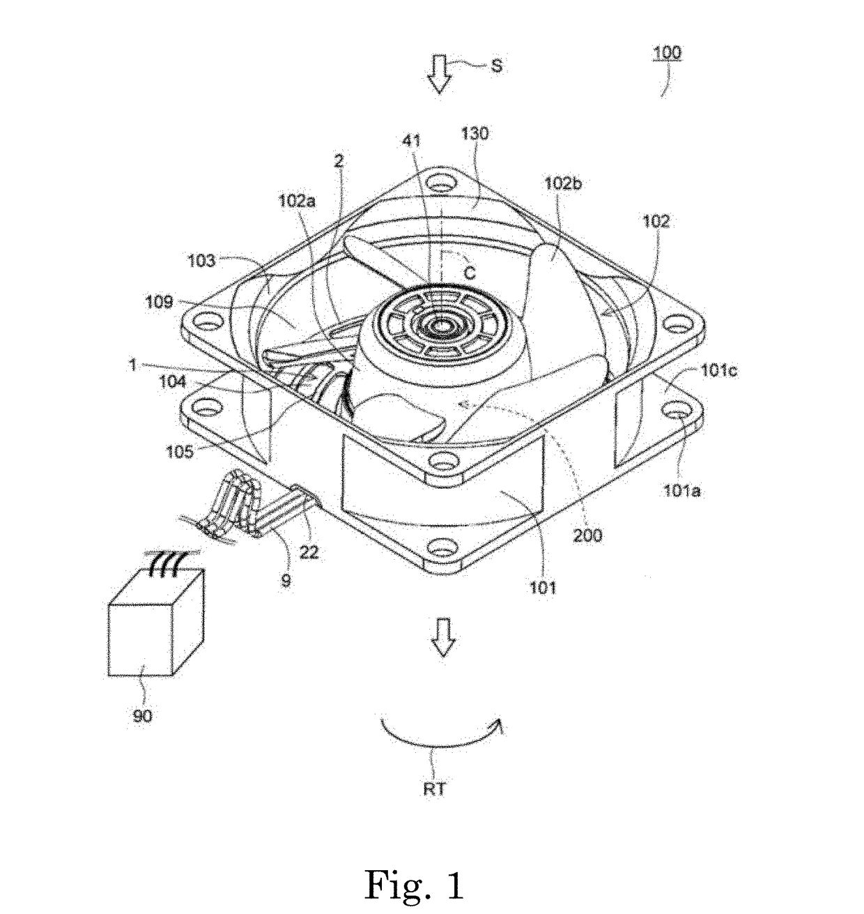
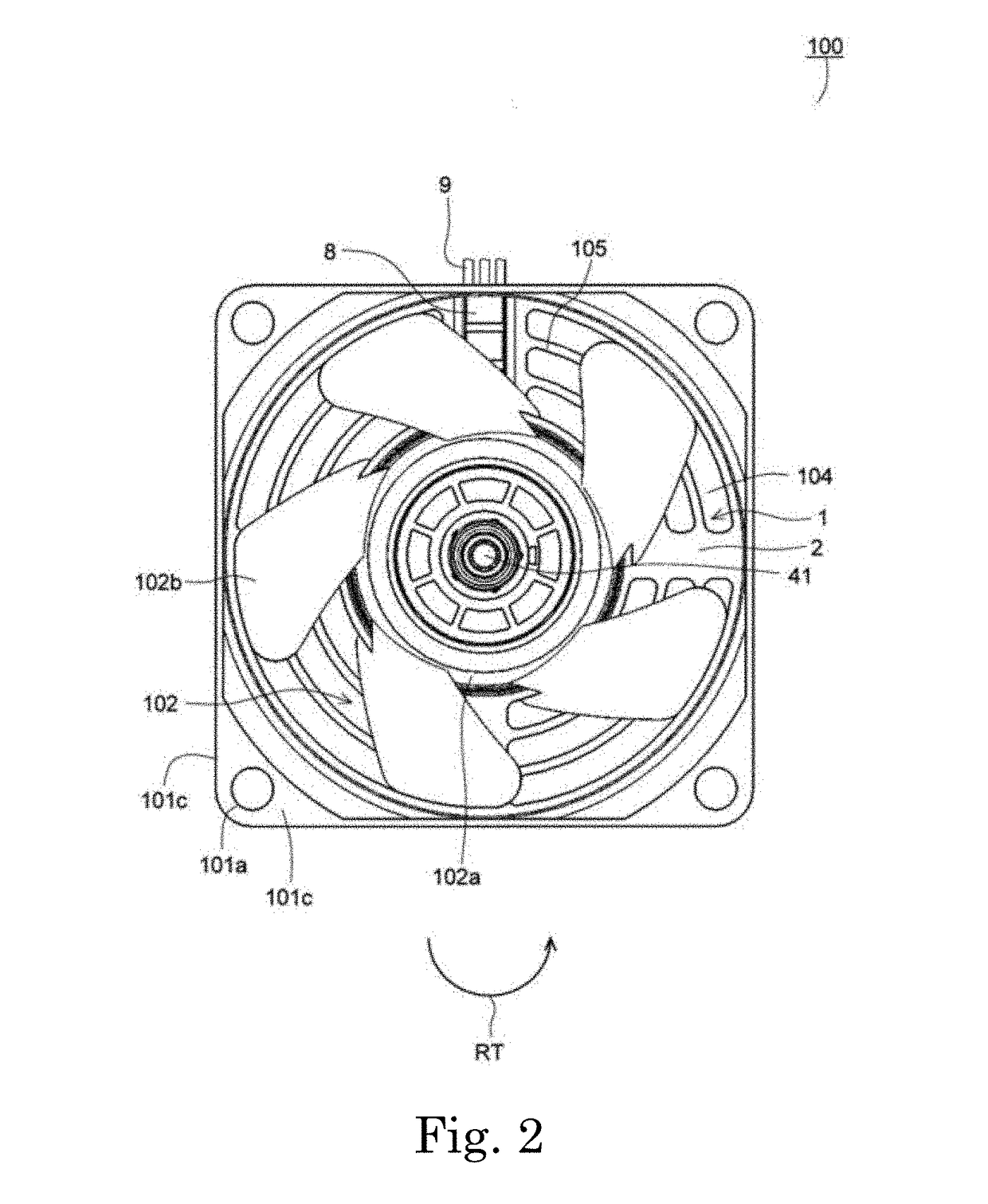
[0039]Hereinafter, exemplary embodiments of the disclosure will be described in detail with reference to drawings. Note that, in the specification, with regard to a base unit 1, a motor 200, and an air blowing device 100, a direction parallel to a central axis C of the base unit 1 will be referred to as an “axial direction”, a direction orthogonal to the central axis C of the base unit 1 will be referred to as a “radial direction”, and a direction along an arc around the central axis C of the base unit 1 will be referred to as a “circumferential direction”.

[0040]Similarly, with regard to an impeller 102, directions that coincide with the axial direction, the radial direction, and the circumferential direction of the air blowing device 100 in a state where the impeller 102 is incorporated in the air blowing device 100 will be simply referred to as an “axial direction”, a “radial direction”, and a “circumferential direction”. In addition, in the specification, the shape of each portion a


PUM


Abstract

A base unit connectable to an external power source includes two or more cables electrically connected to the external power source and extending in a predetermined first direction, and a base plate including a cable installation portion in which the cables are installed. The two or more cables are disposed to be arrayed in a second direction perpendicular to the first direction, the cable installation portion is provided with at least one first wall portion that extends in the first direction, the first wall portion is disposed in at least part of a space between the cables that are adjacent to each other, and the cables and the first wall portion are fixed via molding resin.

Description


Claims


Application Information

Patent Timeline
Owner NIPPON DENSAN CORP
Why Eureka
Try Eureka