Adapter system for a check valve

Active Publication Date: 2018-11-01
AIRBUS OPERATIONS SAS
View PDF27 Cites 0 Cited by
  • Summary
  • Abstract
  • Description
  • Claims
  • Application Information

AI Technical Summary

Benefits of technology

[0009]One object of the present invention is to provide an adapter system for a check valve fitted on a housin

Problems solved by technology

Although such a checking method gives good results, it is relatively lengthy to implement

Method used


Image

  • Adapter system for a check valve
  • Adapter system for a check valve
  • Adapter system for a check valve

Examples


Embodiment Construction

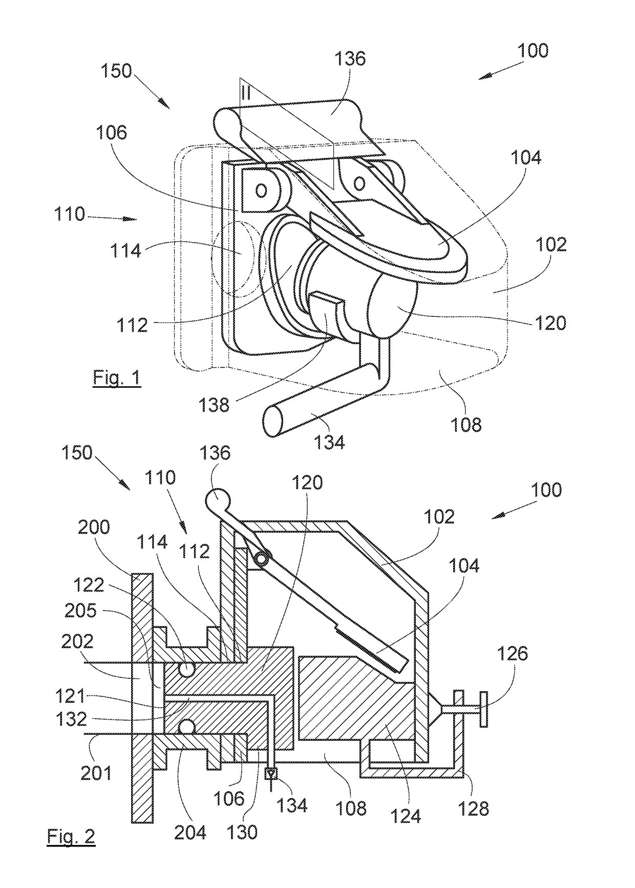
[0037]In the description that follows, the terms relating to a position are taken in reference to a check valve in the position of use, i.e., as it is represented in FIG. 1.

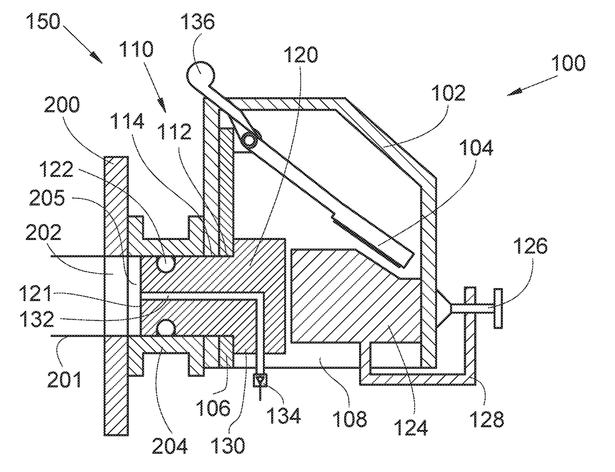
[0038]FIG. 1 shows an adapter system 100 which is fitted inside a housing 102 of a check valve 150. The housing 102 is shown in a transparent view and represented in mixed fine lines.

[0039]FIG. 2 shows the adapter system 100 and the check valve 150 in section through a vertical and median plane.

[0040]The housing 102 is attached onto a wall 200 pierced by a hole 202 forming the end of a pipe 201. The wall 200 is, for example, a wall of an aircraft tank, but the invention applies to any other system and in any other type of industry.

[0041]The housing 102 takes the form of a casing open at the bottom via a window 108.

[0042]In the embodiment of the invention depicted in FIGS. 1 and 2, the housing 102 comprises an upper wall forming a roof and lateral walls extending downwards around the upper wall and one lateral wall o


PUM


Abstract

An adapter system for a check valve which comprises a housing open at the bottom and a lateral wall pierced by a hole, and a flap fitted inside the housing and movable between a shut-off position in which the flap shuts off the hole and a free position in which the flap does not shut off the hole. A plug is provided for being inserted into the hole through an end face and a stop is provided for being placed against the lateral wall of the housing opposite the lateral wall pierced by the hole and comprising an attachment device provided for attaching the stop to the housing and provided so that the plug comes to rest against the stop. Such an adapter system may be installed without it being necessary to dismantle the housing.

Description


Claims


Application Information

Patent Timeline
Owner AIRBUS OPERATIONS SAS
Why Eureka
Try Eureka