Spark plug
a technology of spark plugs and spark plugs, applied in spark plugs, sparking plugs, basic electric elements, etc., can solve the problems of unintentional discharge between the center electrode and the metal shell, breakage of the insulator, etc., to effectively suppress the occurrence of temperature changes, and improve the durability of the insulator
- Summary
- Abstract
- Description
- Claims
- Application Information
AI Technical Summary
Benefits of technology
Problems solved by technology
Method used
Image

Examples
first embodiment
A. First Embodiment
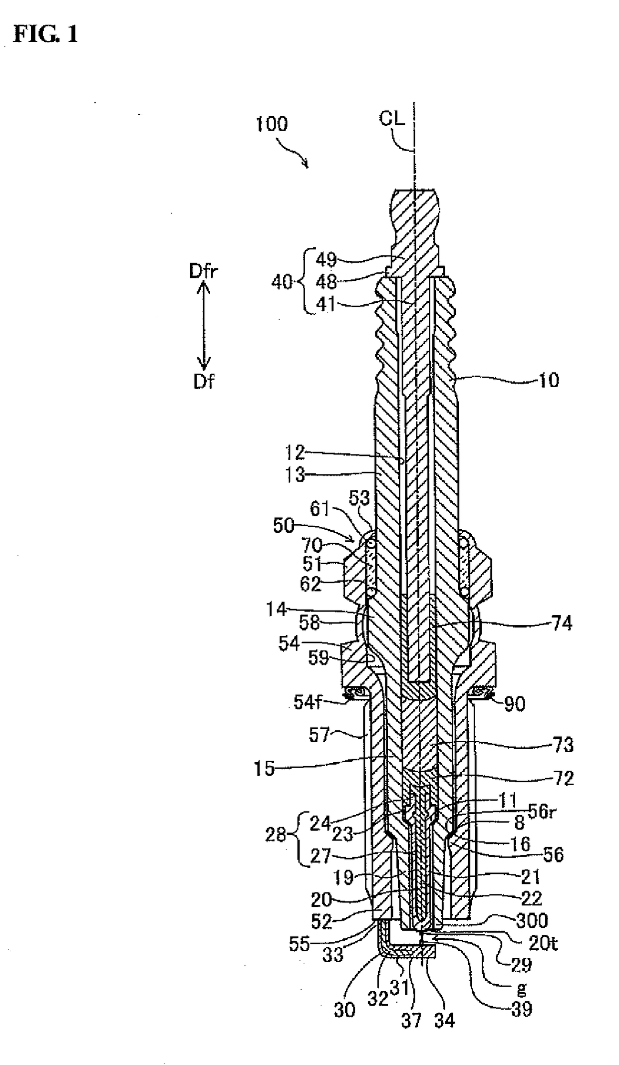
[0036]FIG. 1 shows a cross-sectional view of a spark plug 100 according to a first embodiment of the present invention. In FIG. 1, a center axis CL of the spark plug 100 (also simply referred to as “axis CL”) is indicated by a dot-dash line; and a cross section of the spark plug 100 is taken including the axis CL. In the following description, a direction parallel to the axis CL is also referred to as a direction of the axis CL″ or referred to as an “axial direction” or “vertical direction”; a direction of the radius of a circle about the axis CL is also referred to as a “radial direction”; and a direction of the circumference of a circle about the axis CL is also referred to as a “circumferential direction”. The lower and upper sides in FIG. 1 are respectively correspond to front and rear sides of the spark plug 100. Further, directions toward the front and rear sides of the spark plug 100 with respect to the axis CO are respectively indicated by arrows Df and Dfr i
second embodiment
C. Second Embodiment
[0119]FIG. 4 shows a schematic view of a spark plug 100a according to a second embodiment of the present invention. In FIG. 4, a part of a cross section of the spark plug 100a corresponding to FIG. 2 is shown.
[0120]The spark plug 100a according to the second embodiment is similar to the spark plug 100 according to the first embodiment, except for the configuration of a chamfered area 321a on an insulator 10a. The same parts and portions of the spark plug 100a as those of the spark plug 100 are designated by the same or like reference numerals, and their detailed explanations will be omitted to avoid redundancy.
[0121]In the second embodiment, the spark plug 100a has an insulator 10a formed with an axial hole 12a. A front end portion 300a of the insulator 10a consists of a first (rear-side) section 310 and a second (front-side) section 320a located adjacent to and frontward of the first section 310. An inner circumferential surface Sba of the second section 320a inclu
modification examples
D. Modification Examples
[0123]The present invention is applicable to various forms of spark plugs. For example, the following modifications can be made to the above first and second embodiments.
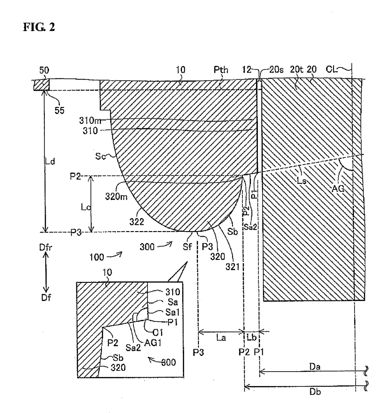
[0124]In the first embodiment (FIG. 2), the insulator 10 may have a cylindrical part of constant inner diameter between the chamfered area 321 and the connection surface region Sa2. In other words, the inner circumferential surface Sb of the second section 320 may include a first (rear-side) surface region constant in inner diameter and connected to the connection surface region Sa2 and a second (front-side) surface region connected to a front side of the first surface region and formed with the chamfered area 321. When viewed in cross section along the axis CL, the R-chamfered area 321 may have a shape defined by a circular arc or defined by a curve other than an arc (e.g. an oval curve). In either case, it is preferable that the R-chamfered area 321 has a curved cross-sectional shape convex to
PUM
 Abstract
Description
Claims
Application Information
 - R&D Engineer
- R&D Manager
- IP Professional
- Industry Leading Data Capabilities
- Powerful AI technology
- Patent DNA Extraction
Browse by: Latest US Patents, China's latest patents, Technical Efficacy Thesaurus, Application Domain, Technology Topic.
© 2024 PatSnap. All rights reserved.Legal|Privacy policy|Modern Slavery Act Transparency Statement|Sitemap