System and method for measuring the level of fluid in a container

a technology of fluid level and container, applied in the field of system and method for measuring the level of fluid in a container, can solve the problems of inaccurate measurement of many of the probe systems, abnormal electrical resistance path between the probes, and -based monitoring systems providing less accurate and less reliable measurements of black and gray water container levels

Active Publication Date: 2019-03-14
RV WHISPER LLC
View PDF0 Cites 0 Cited by
  • Summary
  • Abstract
  • Description
  • Claims
  • Application Information

AI Technical Summary

Benefits of technology

The technical effect of this patented technology is to create a cost-effective way to monitor fluids inside containers by utilizing electrochemistry techniques. This can be done through expensive sensing probes made from materials like platinum or other metals.

Problems solved by technology

The technical problem addressed in this patent is the difficulty and expense associated with accurately measuring the amount of liquid in containers like tanks during refueling operations. Current methods involve using resist-based probes, which have limitations in terms of accuracy and reliability. Capacity-based systems are becoming increasingly popular because they allow for precise measurement of the contents of containers while minimizing the risk of contamination caused by excessive sediment buildup. However, current systems still suffer from issues related to the accumulated deposits left behind on the container's internal surface, leading to incorrect readings.

Method used


Image

  • System and method for measuring the level of fluid in a container
  • System and method for measuring the level of fluid in a container
  • System and method for measuring the level of fluid in a container

Examples


Embodiment Construction

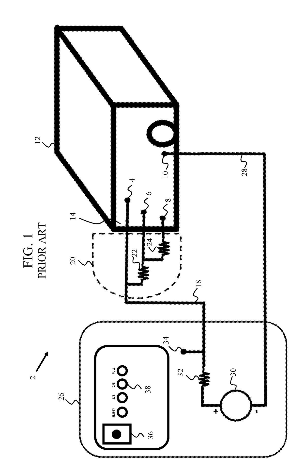
[0021]FIG. 1 is a schematic circuit for a low-cost container monitoring system 2 that utilizes electrical resistance-based probes 4, 6, 8, 10 that are installed through the walls of a fluid container 12 of a recreational vehicle (RV). The electrical resistance-based probes are typically stainless steel and penetrate a plastic, non-conducting container wall 14 at three levels. A ground probe 10 is installed within the container wall at the same level of the lowest probe 8. On the interior of the container (not shown), the probes have a rounded surface with approximately a 1-centimeter diameter exposed to the container contents. On the exterior of the container, the probes can be easily connected to a wire. The three probes that are installed at different levels are connected to each other through a sealed resistor pack 20, containing resistors 22, 24, which connects to a probe wire 18, which in turn connects to a monitor panel 26 located in the living space of the RV. The ground probe 1


PUM


Abstract

A system includes a container having an inner chamber for storing fluid, at least one measuring probe arranged within the chamber and one ground probe arranged within or near a bottom of the chamber. There is at least one impedance electrically connected with a processor which is electrically connected with the at least one measuring probe. A signal generator has a first voltage terminal electrically connected with the at least one impedance and a second voltage terminal electrically connected with the ground probe. When a signal is sent from the signal generator to the measuring probe, an electrochemical reaction occurs at the measuring probe and ground probe and stores a charge if the measuring probe and/or ground probe are immersed in fluid. The processor measures the voltage, current and power of the signal to calculate the resistance and capacitance of the fluid within the container to determine the level of fluid in the container. A method for measuring the level of fluid in the container includes the steps of applying at least one time-varying voltage signal to the one or more measuring probes, creating an electrochemical reaction between the ground probe and each measuring probe, storing energy around each probe that is submerged in fluid, measuring the current and power of the signals, and determining the level of fluid in the container based on the calculated capacitance and resistance of the fluid within the container.

Description


Claims


Application Information

Patent Timeline
Owner RV WHISPER LLC
Why Eureka
Try Eureka