Measurement support device, endoscope system, processor for endoscope system
a technology of endoscope system and support device, which is applied in the direction of television system, image enhancement, instruments, etc., can solve the problems of complex system configuration and processing, high burden on the subject, and often irregular subject matter, and achieve the effect of simple configuration
- Summary
- Abstract
- Description
- Claims
- Application Information
AI Technical Summary
Benefits of technology
Problems solved by technology
Method used
Image

Examples
first embodiment
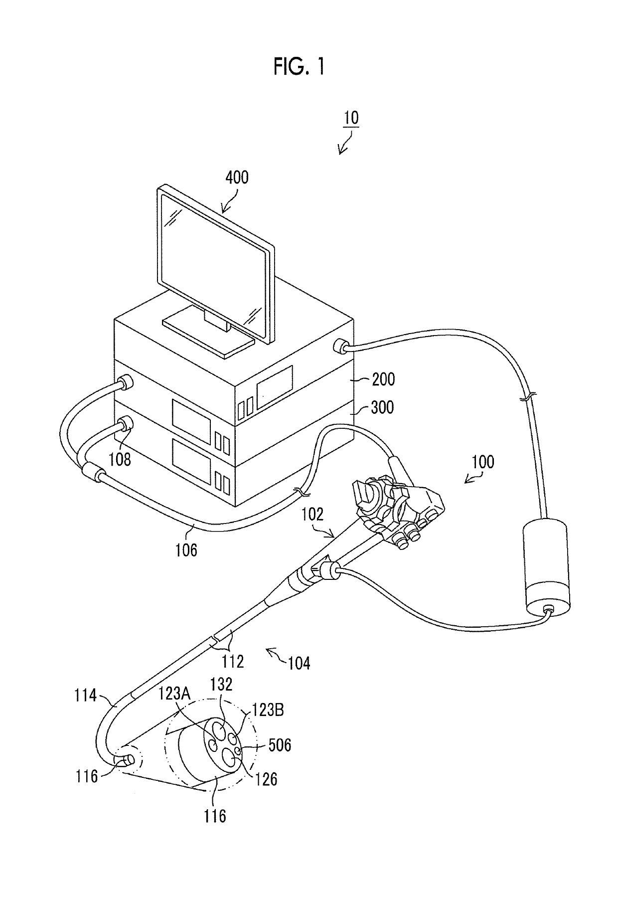
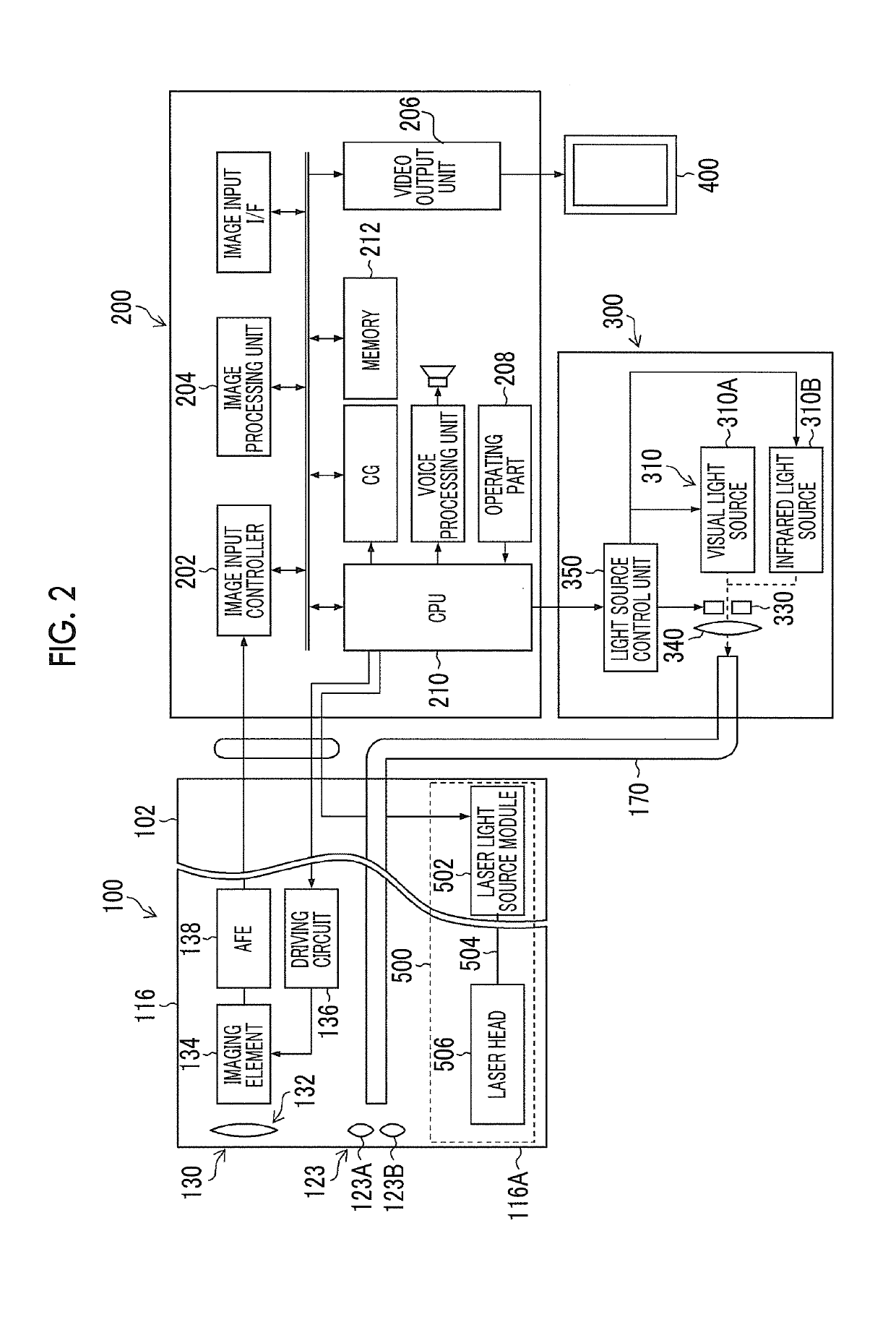
[0061]FIG. 1 is an external view illustrating an endoscope system 10 (a measurement support device, an endoscope system, and a processor for an endoscope system) related to a first embodiment, and FIG. 2 is a block diagram illustrating the configuration of main parts of the endoscope system 10. As illustrated in FIGS. 1 and 2, the endoscope system 10 comprises an endoscope body 100 (endoscope), a processor 200 (processor for an endoscope system), a light source device 300, and a monitor 400 (display device).
[0062]
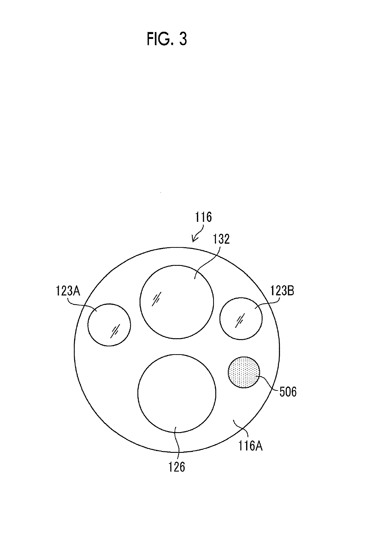
[0063]The endoscope body 100 comprises a proximal operating part 102 (operating part), and an insertion part 104 (insertion part) provided continuously with at the proximal operating part 102. An operator grips the proximal operating part 102 to operate the endoscope body 100, and inserts the insertion part 104 into the body of a subject to observe the body. The insertion part 104 is constituted of a flexible part 112 (flexible part), a bending part 114 (bending part), and a d
example 1
[0127]
[0128]FIG. 18 is a flowchart illustrating processing of the coordinate generation and storage in Embodiment 1. In Example 1, an actually measured point (first point) and a point (second point) generated by interpolating the actually measured point are stored as coordinates of points indicating a distorted circular marker. Actual measurement, transformation (each processing in the flowchart of FIG. 18), and the like of the coordinates can be performed by the processor 200 (the CPU 210, the image processing unit 204), and the generated coordinates are stored in the memory 212 (storage unit).
[0129]First, the measurement auxiliary light is radiated at the imaging distance set in the distance range (refer to the range R1 of FIG. 9) in which measurement by a distorted circular marker is effective with respect to the actual size to be a processing target (although the actual size is described below as 5 mm in diameter, the actual size may have different values in accordance with measure
example 2
[0133]
[0134]Next, Example 2 of the coordinate generation and storage of the points indicating the distorted circular marker will be described. In Example 2, the coordinates of the circular marker are calculated in the region transformed to the square lattice by projective transformation, the calculated coordinates are inversely transformed, and the coordinates of the distorted circular marker in the distorted lattice region are acquired. Processing, such as generation, transformation (respective kinds of processing in the flowchart of FIG. 21), and the like of the coordinates can be performed by the processor 200 (the CPU 210, the image processing unit 204), and the generated coordinates are stored in the memory 212 (storage unit).
[0135]FIG. 21 is a flowchart illustrating the processing of the coordinate generation and storage in Example 2. First, similarly to Step S100 of Example 1, the measurement auxiliary light is radiated, and a square lattice-like chart is captured (Step S200). I
PUM
 Abstract
Description
Claims
Application Information
 - R&D Engineer
- R&D Manager
- IP Professional
- Industry Leading Data Capabilities
- Powerful AI technology
- Patent DNA Extraction
Browse by: Latest US Patents, China's latest patents, Technical Efficacy Thesaurus, Application Domain, Technology Topic.
© 2024 PatSnap. All rights reserved.Legal|Privacy policy|Modern Slavery Act Transparency Statement|Sitemap