Over fire arrangement and method

a fire arrangement and over fire technology, applied in the direction of combustion types, combustion processes, combustion using lump and pulverulent fuel, etc., can solve the problems of increasing including carbon monoxide, negative effects of nox emissions from combustion processes, and reducing combustion efficiency, so as to improve the burnout rate of fuel, reduce the amount of unburned in the combustion process, and improve the effect of combustion efficiency

Active Publication Date: 2019-10-24
TEKNOLOGIAN TUTKIMUSKESKUS VTT
View PDF0 Cites 1 Cited by
  • Summary
  • Abstract
  • Description
  • Claims
  • Application Information

AI Technical Summary

Benefits of technology

This patent describes an improved method for burning fuels by adding extra airflow into areas where there are no flames or other sources of heat near these surfaces. These added airflow helps to increase the efficiency of the combustion process while reducing unwanted emissions such as nitrous oxide (NOx).

Problems solved by technology

The technical problem addressed in this patent is how to improve the burning efficiency and reduce unwanted emissions caused by nitrogen oxides during combustion processes while maintaining effective flames throughout all areas where the fuel is being burnt.

Method used


Image

  • Over fire arrangement and method
  • Over fire arrangement and method
  • Over fire arrangement and method

Examples


Embodiment Construction

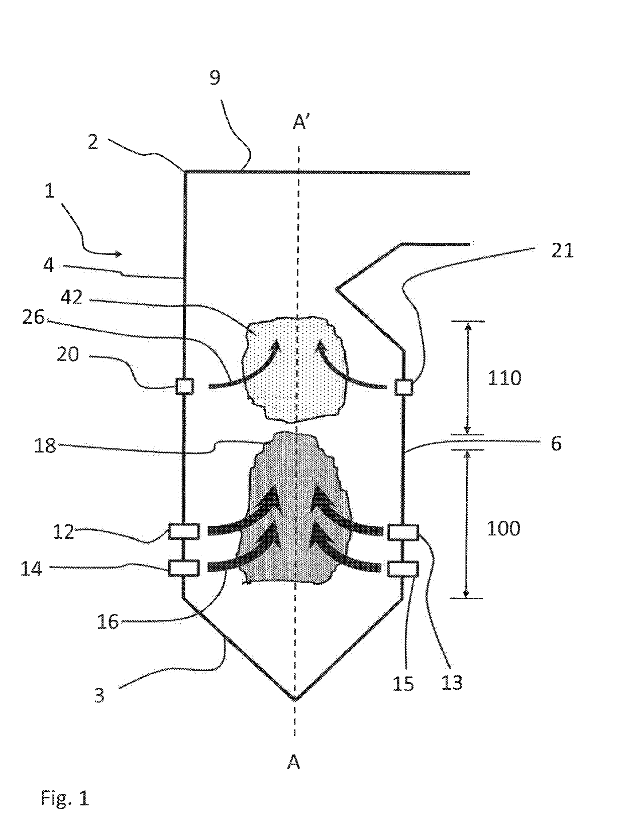
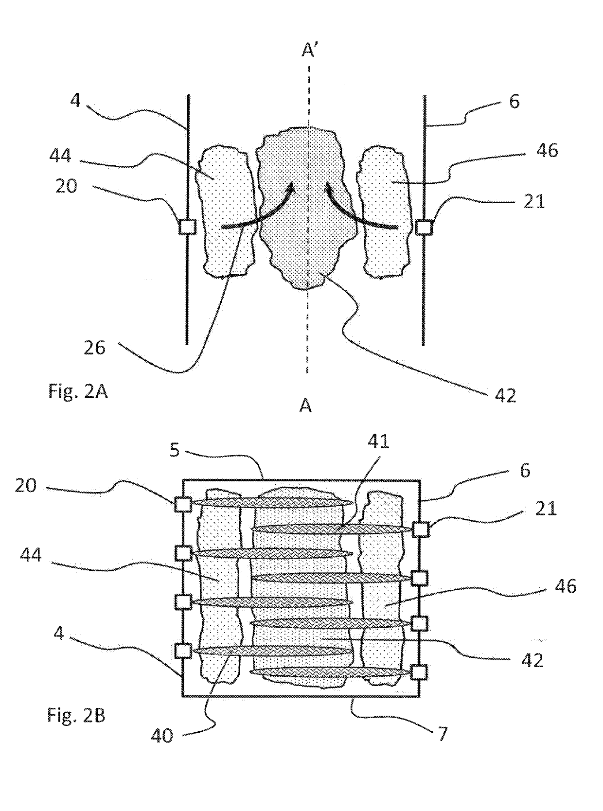
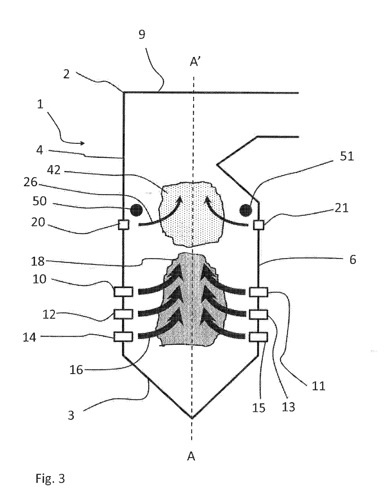
[0028]FIG. 1 shows a prior art furnace 1 having a bottom 3 and top 9, and opposing front wall 4 and rear wall 6 as well as opposing first and second side wall 5, 7 (shown in FIG. 2B). The front wall 4 and rear wall 6 as well as opposing first and second side wall 5, 7 form together an enclosure 2 of the furnace 1, as shown in FIG. 2B. The furnace 1 comprises burners 14, 12, 10, 15, 13, 11 provided to the opposing first and second walls 4, 6 of the furnace for combusting fuel. In this embodiment the furnace comprises at least one first primary burner 14 provided to the first wall 4 and at least one second primary burner 15 provided to the second wall 6 for forming a first level of burners and first combustion stage. The furnace 1 further comprises at least one first secondary burner 14 provided to the first wall 4 and at least one second secondary burner 15 provided to the second wall 6, the secondary burners being arranged above the primary burners 14, 15 in vertical direction for stag


PUM


Abstract

The present invention relates to an over fire air arrangement for a furnace (1), the furnace (1) having opposing first wall (4) and second wall (6) and opposing first side wall (5) and second side wall (7) between the first and second walls (4, 6) for forming a furnace enclosure (2). The over fire air arrangement comprising at least one first over fire air port (20) provided to the first wall (4) for supplying a first over fire air flow (40) into the furnace (1) and at least one first additional over fire air port (50) provided to at least one of the first and second side walls (5, 7) in the vicinity of the first wall (4), the at least one first additional over fire air port (50) being arranged to supplying a first additional over fire air flow (60) into the furnace (1) transversely to the first over fire air flow (40).

Description


Claims


Application Information

Patent Timeline
Owner TEKNOLOGIAN TUTKIMUSKESKUS VTT
Why Eureka
Try Eureka