Gate-Operated Kinetic Energy Switches

a kinetic energy switch and gate technology, applied in the direction of hinges, wing accessories, burglar alarm mechanical actuation, etc., can solve the problems of affecting the ability of persons and vehicle drivers, affecting individual ability quite suddenly and unexpectedly, and affecting the ability of individuals

Inactive Publication Date: 2020-03-12
ERGOMAT INC
View PDF0 Cites 1 Cited by
  • Summary
  • Abstract
  • Description
  • Claims
  • Application Information

AI Technical Summary

Benefits of technology

The technical effect that this design allows for limited movements on both sides during operation without affecting any other parts or structures near it.

Problems solved by technology

This patented technical problem addressed in this patent describes how to prevent accidentals during loading and unloading cargo carrying equipment like truck trailers due to potential collision hazards involving obstacles called "passenger lants". Specifically, there exist various ways to avoid accidents including those related toklifts driving alongside empty loads waiting behind them. However, current methods require manual interference, making it difficult if necessary.

Method used


Image

  • Gate-Operated Kinetic Energy Switches
  • Gate-Operated Kinetic Energy Switches
  • Gate-Operated Kinetic Energy Switches

Examples


Embodiment Construction

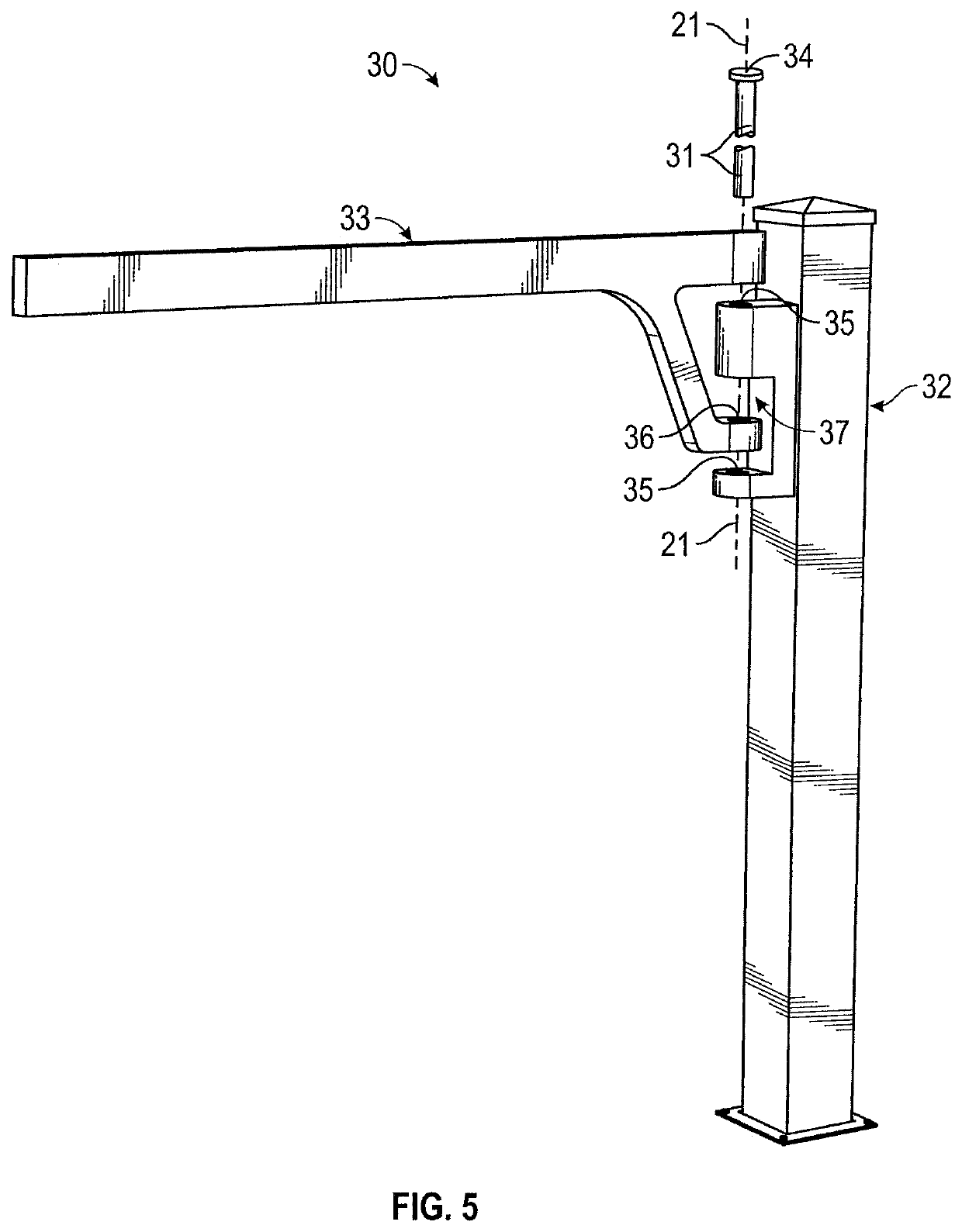
[0060]As has been explained, in preferred practice the present invention relates to the provision and use of post and gate assemblies, each of which includes an upstanding floor mountable post installed adjacent a separate one of the several perpendicular travel path junctures defined by a grid of travel paths followed by fork lift vehicles as they move along and among a set of upstanding storage structures in a large, industrial storage area where palletized goods are temporarily held on pallets until the goods are needed elsewhere.

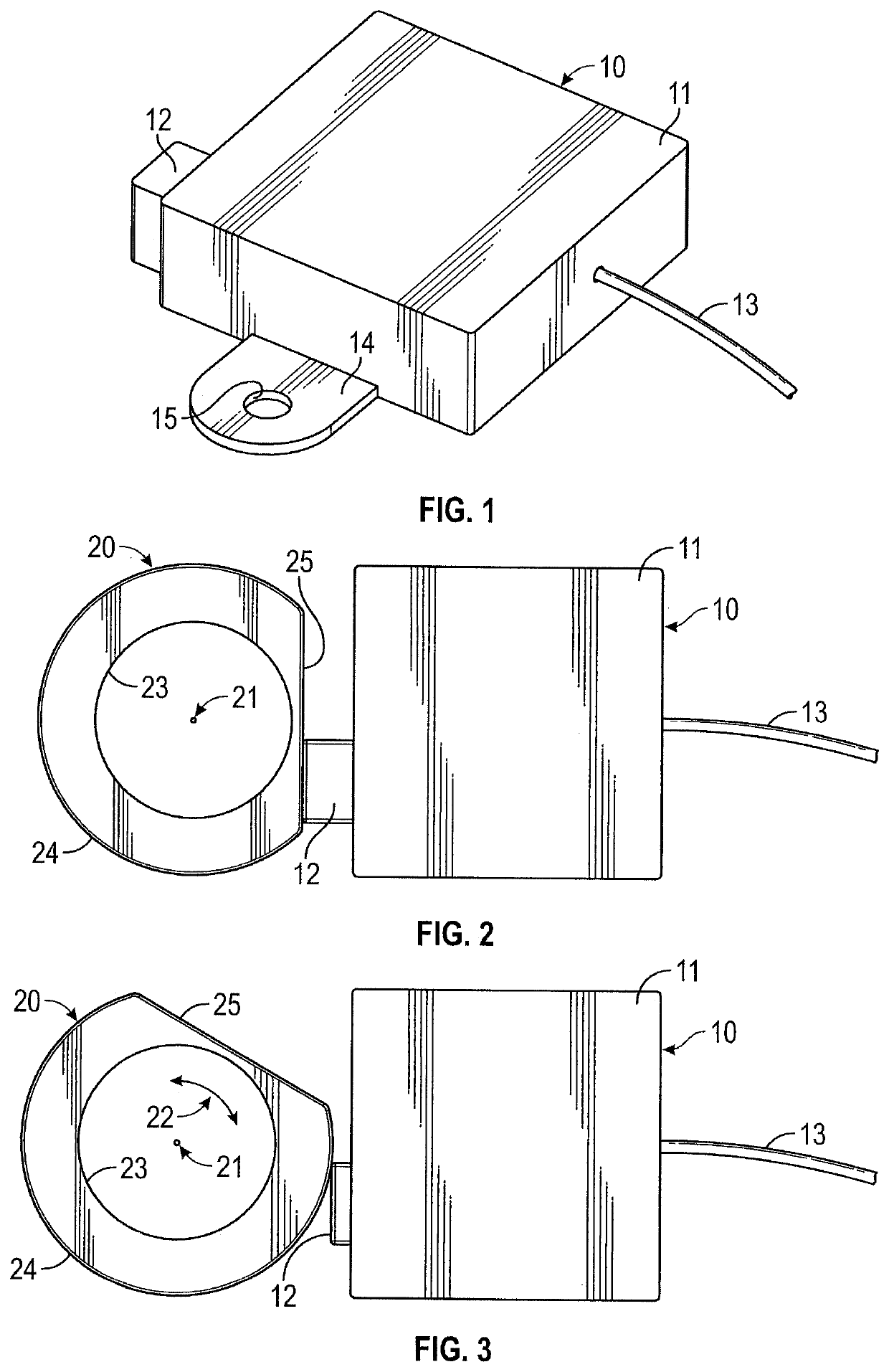
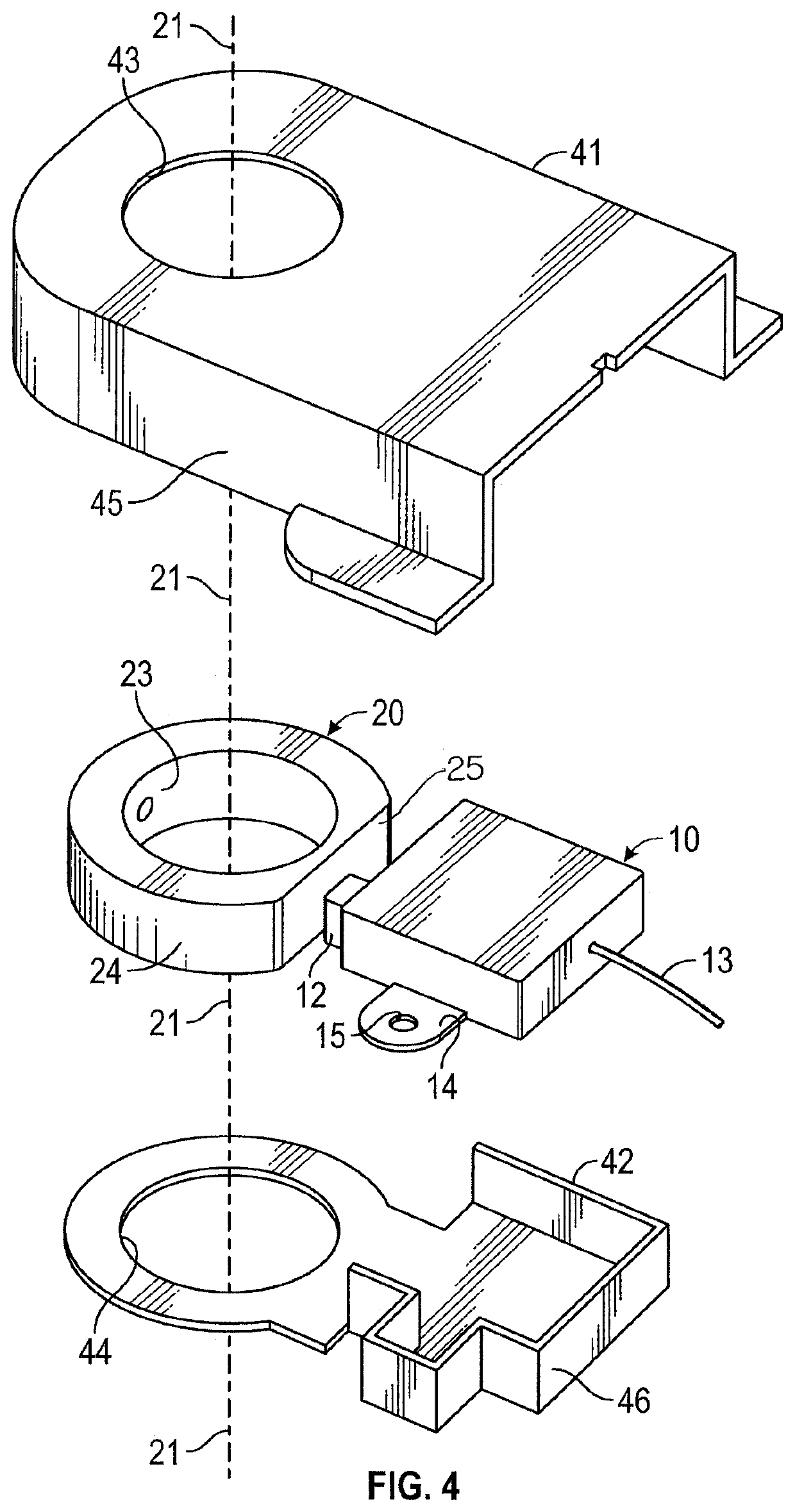
[0061]As also has been explained, in preferred practice, the floor-mountable post and gate assemblies of the present invention each include a post component and a gate component that are pivotally connected, together with a kinetic energy switch that is operated by a cam interposed between the post and gate components to send uniquely encoded radio signals to remotely located receiving units that operate warning devices to notify drivers of fork lift vehicl


PUM


Abstract

A gate is pivotally mounted on an upstanding post located adjacent a juncture of intersecting travel paths. To prevent collisions of persons and/or vehicles moving along the intersecting travel paths at the travel path juncture, a kinetic energy harvesting switch is carried by the upstanding post and has a spring-projected push button or plunger-type operator that is depressed relative to a housing of the switch when the gate begins to open to admit a person and/or a vehicle to the travel path juncture. Energy harvested by the switch is utilized to transmit a radio frequency signal that can be received by a device that displays a visual warning and/or emits an audible warning, advising that collision avoidance measures are likely to be needed to prevent a collision at the travel path juncture.

Description


Claims


Application Information

Patent Timeline
Owner ERGOMAT INC
Why Eureka
Try Eureka