Power cable with non-conductive armor

a power cable and armor technology, applied in the direction of insulated conductors, carbon-silicon compound conductors, cables, etc., can solve the problems of reducing the capacity of carrying current and affecting the service life of the power cable. , to achieve the effect of extending the length of the single core conductor

Inactive Publication Date: 2020-04-23
SAUDI ARABIAN OIL CO
View PDF27 Cites 0 Cited by
  • Summary
  • Abstract
  • Description
  • Claims
  • Application Information

AI Technical Summary

Benefits of technology

This invention relates to methods for protecting military vehicles from damage caused by high voltages during use or transportation. It involves adding layers on top of existing materials that prevent electrical arcs between them. These added layers are designed with specific shapes and sizes to help reduce any potential hazards associated therewith while still maintain their effectiveness against these threats.

Problems solved by technology

This patented describes how well-insulated electrical wires (power cords) made from iron plating were protected by layers called Armoring Layer that protect them against external impacts like falling rocks during transportation. However, there was also some concern about these types of materials being damaged due to environmental factors like rainwater.

Method used


Image

  • Power cable with non-conductive armor

Examples


Embodiment Construction

[0014]Embodiments of the present disclosure will now be described more fully hereinafter with reference to the accompanying drawings which illustrate embodiments of the disclosure. Systems and methods of this disclosure may, however, be embodied in many different forms and should not be construed as limited to the illustrated embodiments set forth herein. Rather, these embodiments are provided so that this disclosure will be thorough and complete, and will fully convey the scope of the disclosure to those skilled in the art. Like numbers refer to like elements throughout, and the prime notation, if used, indicates similar elements in alternative embodiments or positions.

[0015]In the following discussion, numerous specific details are set forth to provide a thorough understanding of the present disclosure. However, it will be obvious to those skilled in the art that embodiments of the present disclosure can be practiced without such specific details. Additionally, for the most part, det


PUM


Abstract

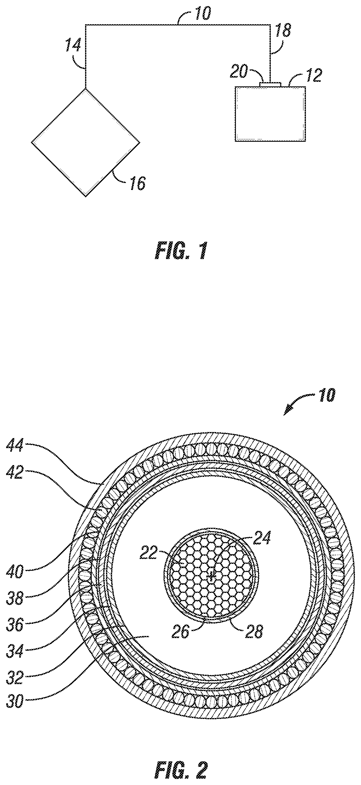
Systems and methods for providing power to a device in a hydrocarbon development operation include a cable having a single core conductor. The single core conductor is an elongated member with a central axis and is operable to conduct electricity. An insulation member circumscribes the single core conductor and extends the length of the single core conductor. The insulation member has an annular cross section centered around the central axis of the single core conductor. An armor layer circumscribes the single core conductor and extends the length of the single core conductor. The armor layer has an annular cross section centered around the central axis of the single core conductor and is formed of a non-conductive material incapable of conducting a current. The armor layer is radially exterior of the insulation member.

Description


Claims


Application Information

Patent Timeline
Owner SAUDI ARABIAN OIL CO
Why Eureka
Try Eureka