Boiler system for both heating and hot water

a boiler system and boiler technology, applied in space heating and ventilation, heating types, lighting and heating apparatus, etc., can solve the problems of reducing the ease of installation and increasing the purchase cost of pumps, and achieve the effect of smooth preheating and circulating

Inactive Publication Date: 2020-06-18
KYUNGDONG NAVIEN
View PDF0 Cites 1 Cited by
  • Summary
  • Abstract
  • Description
  • Claims
  • Application Information

AI Technical Summary

Benefits of technology

The technical effect of this patented solution described in this patents relates to an improved method for efficiently utilizing energy from multiple sources during simultaneous warm/hot water supply systems with two different ways of connecting them together: either way allows for efficient use of each source separately while also simplifying its assembly process. This results in cost savings compared to traditional methods like separate installations of individual components (circles) used individually. Additionally, it provides versatility across all types of steam generators including those made up solely of solid fuel elements.

Problems solved by technology

This technical problem addressed in this patented technology relates to improving efficiency during operation of traditional thermal power systems used for providing high-quality energy sources like electricity. Specifically, it focuses on reducing costs associated with purchasing multiple separate components including one dedicated to circulated fluid (hot) water while another component uses only cold water for coolant purposes.

Method used


Image

  • Boiler system for both heating and hot water
  • Boiler system for both heating and hot water
  • Boiler system for both heating and hot water

Examples


first embodiment

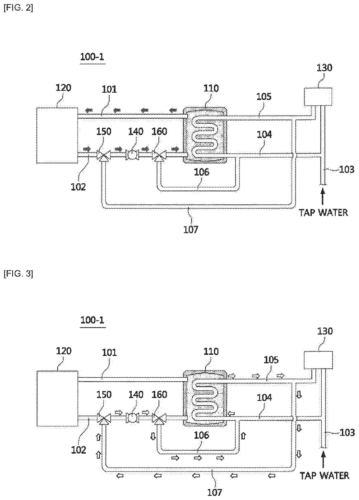
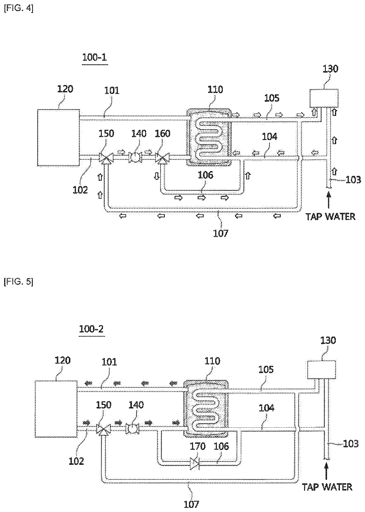
[0038]Referring to FIGS. 2 to 4, a boiler system 100-1 for both heating and hot water according to the present invention includes a hot water storage type heat exchanger 110 which stores heating water supplied to a heating destination 120, heats the heating water using a heat source (not shown), and generates hot water through a heat exchange between the heated heating water and tap water.

[0039]A heating water supply pipe 101 and a heating water return pipe 102 are connected between the hot water storage type heat exchanger 110 and the heating destination 120 to form a heating water channel.

[0040]A tap water pipe 103 and a hot water supply pipe 105 are connected to a hot water destination 130.

[0041]A tap water supply pipe 104 is branched from the tap water pipe 103 and is connected to pass through the inside of the hot water storage type heat exchanger 110. The tap water supply pipe 104 inside the hot water storage type heat exchanger 110 is connected to the hot water supply pipe 105.

third embodiment

[0067]Referring to FIGS. 8 to 11, a boiler system 200-1 for both heating and hot water according to the present invention includes a main heat exchanger 210 which heats heating water supplied for heating or supplied for exchanging heat by using combustion heat and a hot water heat exchanger 220 which generates hot water by exchanging heat between the heated heating water, which is heated by the main heat exchanger 210, and tap water. Reference symbol “F” denotes an air blower configured to supply combustion air, and reference symbol “B” denotes a burner configured to burn a mixture gas of combustion air and a gas.

[0068]A heating water supply pipe 201 and a heating water return pipe 202 are connected between the main heat exchanger 210 and a heating destination 230 to form a heating water channel.

[0069]A heating water bypass pipe 203 is connected to the heating water supply pipe 201 such that heating water supplied from the main heat exchanger 210 flows toward the heating water return p


PUM


Abstract

The objective of the present invention is to provide a boiler system for bath heating and hot water that is capable of performing heating and hot water preheating by using a single circulation pump for both without the need to separately include a circulation pump for heating and a circulation pump for hot water preheating. In order to achieve the above objective, the present invention provides a boiler system for both heating and hot water, comprising: a heat exchanging unit; a heating water channel connected between the heat exchanging unit and a place to be heated; a tap water supply pipe for supplying tap water to the heat exchanging unit; a hot water supply pipe for supplying hot water to a place requiring hot water from the heat exchanging unit; a hot water recirculation channel connected to the hot water supply pipe at a first branch point branched from one side of the heating water channel; a hot water bypass channel connected from the second branch point branched from the other side of the heating water channel to the tap water supply pipe; and a circulation pump disposed between the first branch point and the second branch point.

Description


Claims


Application Information

Patent Timeline
Owner KYUNGDONG NAVIEN
Why Eureka
Try Eureka