Microscope system and method for operating a microscope system

Active Publication Date: 2020-06-25
CARL ZEISS MICROSCOPY GMBH
View PDF0 Cites 1 Cited by
  • Summary
  • Abstract
  • Description
  • Claims
  • Application Information

AI Technical Summary

Benefits of technology

[0012]An object of the invention is to provide a microscope system and a method for operating a microscope system, which, in respect of the data transfer between components of the microscope system, facilitate the highest possible quality and high transfer rates.

Problems solved by technology

The ever-increasing demands on the transfer rate and temporal accuracy cannot be met in satisfactory fashion by known microscope systems, particularly if the employed pixel clocks are particularly short.
However, the arrival of a synchronization signal cannot be sensibly predicted by a module.
Relatively long unused time periods arise as a result.
However, transfer delays and calculation durations, which cause a delay 2, arise in the process.
However, very short pixel lengths 1 have not been possible previously as a result of the delay 2.
However, even conventional systems specifically developed for certain applications cannot meet the ever-increasing requirements.
A latency between a transmitted datum and a synchronizing clock is particularly problematic since a simultaneous effect or an effect at a certain time cannot be ensured.

Method used


Image

  • Microscope system and method for operating a microscope system
  • Microscope system and method for operating a microscope system

Examples


Example

[0045]Identical and identical-acting constituent parts are generally identified by the same reference signs in the figures.

DETAILED DESCRIPTION OF EMBODIMENTS OF THE INVENTION

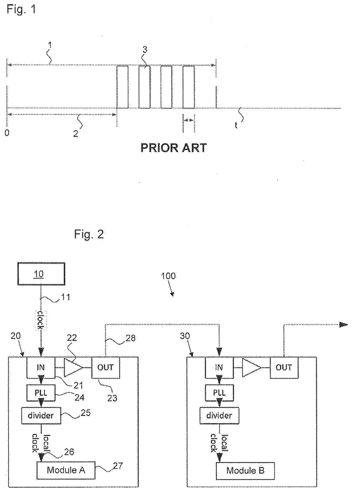
[0046]FIG. 2 illustrates an exemplary embodiment of a microscope system 100 according to the invention. As essential components, the latter has a plurality of microscope modules 20, 30 and a central clock generator 10.

[0047]In principle, the microscope modules 20, 30 can be any constituent parts of a light microscope that have electronic components. By way of example, the module 20 can be a laser scanning unit and the module 30 can be a light source unit which has a plurality of lasers and the actuation unit thereof, for example.

[0048]The modules 20, 30 communicate with one another and / or with a central computing unit (not illustrated). Data communication times must be synchronized with one another. By way of example, scanning mirrors of one module and a light source of another module should be actuated in a man


PUM


Abstract

A microscope system having a plurality of microscope modules connected to one another for data transfer purposes. The microscope system includes a central clock generator, the clock signal of which is provided to all microscope modules. The microscope modules are configured to use the clock signal or a clock derived therefrom as an internal clock. Moreover, a corresponding method for operating such a microscope system is described.

Description


Claims


Application Information

Patent Timeline
Owner CARL ZEISS MICROSCOPY GMBH
Why Eureka
Try Eureka