Method for adapting a fuel injector control signal

a technology of control signal and fuel injector, which is applied in the direction of fuel injection control, electric control, machines/engines, etc., can solve the problems of inability to have a fast enough reaction time at the frequency used, inability to adapt simple analog filters of any order, and possible attenuation, etc., to achieve simple, reliable and effective

Active Publication Date: 2020-10-29
VITESCO TECH GERMANY GMBH
View PDF0 Cites 0 Cited by
  • Summary
  • Abstract
  • Description
  • Claims
  • Application Information

AI Technical Summary

Benefits of technology

The technical effect of this patented technology is that it provides an easy-to-use way to protect from damage caused by unwanted electrical signals during operation without causing any problems with other components on the system being controlled.

Problems solved by technology

The technical problem addressed in this patents relates to improving the accuracy and reliability of electronic systems used in vehicles equipped with diesel engines without generating excessive noise caused by factors like electricity fluctuations and electromechanism issues. This issue arising from variations in timing among different components affects how long the time required before starting operation after startup.

Method used


Image

  • Method for adapting a fuel injector control signal
  • Method for adapting a fuel injector control signal
  • Method for adapting a fuel injector control signal

Examples


Embodiment Construction

[0049]The vehicle described in the example below is a motor vehicle including a combustion engine with a plurality of cylinders. However, it should be noted that the invention applies more broadly to any type of vehicle with a combustion or hybrid engine, the number of cylinders being greater than or equal to one.

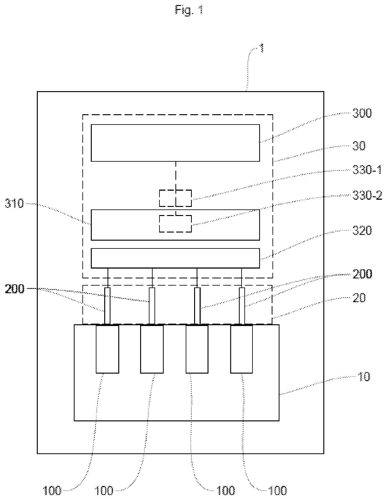
[0050]FIG. 1 schematically shows an example of a vehicle 1 according to the invention comprising a combustion engine 10, a system 20 for injecting fuel into said engine 10 and a computer 30, known as the “engine control computer”, for controlling said injection system 20.

[0051]The engine 10 comprises a plurality of cylinders 100 in each of which a mixture of oxidant (air) and fuel is combusted.

[0052]The injection system 20 comprises a plurality of fuel injectors 200, at least one injector 200 being mounted on each of the cylinders 100.

[0053]The injection system 20 may also comprise a pump (not shown) and an injection rail (not shown).

[0054]The intake of air into a cylinder 100


PUM


Abstract

Disclosed is a method for adapting a control signal of a control circuit for at least one injector of a combustion engine of a motor vehicle, the control signal being a voltage-pulse signal of variable frequency varying between a minimum frequency and a maximum frequency and which is characterized over a given period by its duty cycle. For a given period of the control signal, the method includes determining the start time of the given period and of detecting the first pulse in the given period from the start time and, when the duration of the detected first pulse is included in a minimum time interval beginning at the start of the given period and the duration of which is dependent on the maximum frequency, modifying the duration of the detected first pulse so that the duration becomes equal to the duration of the minimum time interval.

Description


Claims


Application Information

Patent Timeline
Owner VITESCO TECH GERMANY GMBH
Why Eureka
Try Eureka