Oct system and oct method

a technology of oct and oct signal, applied in the field of oct system, can solve the problems of parasitic reflection, adverse effects on the quality of oct signal, disturbance of interference signal, etc., and achieve the effect of avoiding any disadvantage to the quality of oct measuremen

Active Publication Date: 2021-07-01
HAAG STREIT AG
View PDF0 Cites 0 Cited by
  • Summary
  • Abstract
  • Description
  • Claims
  • Application Information

AI Technical Summary

Benefits of technology

It describes two ways to measure objects accurately: 1) By dividing them down multiple times at least twice within each detection region or 2) Using only one type of laser (one-photon excitation). These techniques allow us to make precise measurements even when there may have many reflecting surfaces present inside the optical fibers used during medical procedures.

Problems solved by technology

In this patented technology, there was developed a new way to measure objects accurately through Optical Coherty techniques called OpticoCtrac technique or Interferometric Lens Imaging Technique. These methods involve measuring changes made on different parts of the subject's body during medical procedures like surgery. However, these technical problem addressed by the inventors involves unwanted signals due to certain types of reflection off surfaces inside the patient being observed.

Method used


Image

  • Oct system and oct method
  • Oct system and oct method
  • Oct system and oct method

Examples


Embodiment Construction

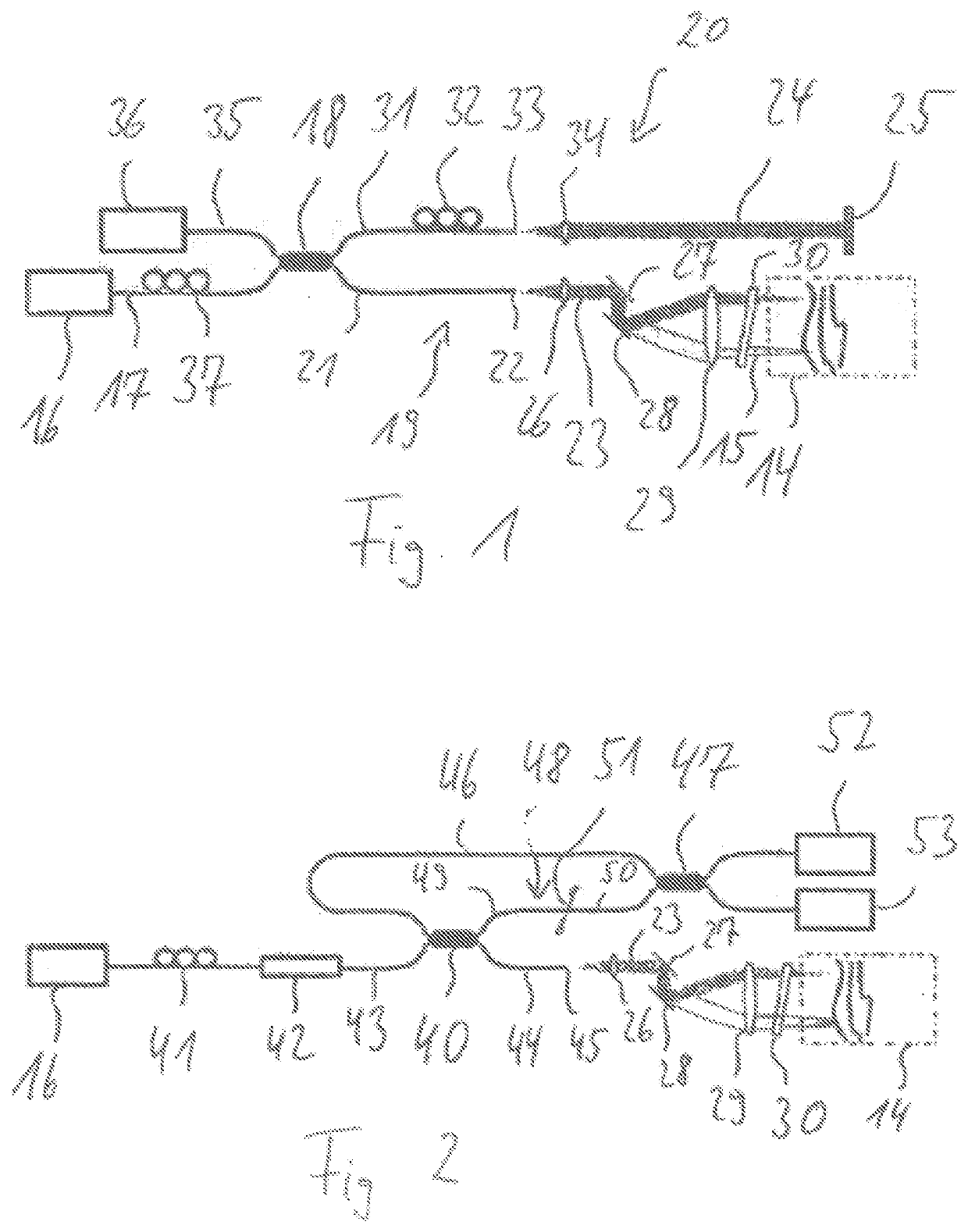
[0053]An OCT system shown in FIG. 1 serves for examining a measurement object 14 in the form of a human eye. By virtue of OCT light 15 being directed onto the measurement object 14, image information is obtained, which extends along the axis of the OCT beam into the depth of the measurement object 14. By virtue of the OCT beam being scanned over the measurement object 14 in a direction perpendicular thereto, a three-dimensional image of the measurement object 14 can be obtained from a multiplicity of individual measurement recordings.

[0054]The OCT system comprises an OCT light source 16, embodied as a swept-source light source. The swept-source light source 16 generates narrowband light that is spectrally tunable. That is to say that at each instant narrowband light is emitted, the frequency of which changes over time, such that the swept-source light source is tuned over a frequency range during a tuning time.

[0055]The OCT light 15 emitted by the OCT light source 16 is linearly polari


PUM


Abstract

The invention relates to an OCT system with an OCT light source for emitting OCT light into an object beam path and a reference beam path. The system comprises a detector for detecting an interference signal produced by the object beam path and the reference beam path. A polarization-dependent delay element is arranged in the object beam path. The invention also relates to a corresponding OCT method. The invention allows the effects of parasitic reflections to be reduced.

Description


Claims


Application Information

Patent Timeline
Owner HAAG STREIT AG
Why Eureka
Try Eureka