Noise reduction method

a cryogenic cooling and noise reduction technology, applied in the direction of gas cycle refrigeration machines, refrigeration machines, refrigeration safety arrangements, etc., can solve the problems of noise monitoring, previously considered undesirable, source of noise in highly sensitive experiments and procedures, etc., and achieve the effect of reducing noise and reducing the amplitude of said vibrations

Pending Publication Date: 2021-10-07
OXFORD INSTR NANOTECH TOOLS
View PDF4 Cites 1 Cited by
  • Summary
  • Abstract
  • Description
  • Claims
  • Application Information

AI Technical Summary

Benefits of technology

The technical effect of this patented technology is that it can help reduce noise caused by the movement of parts inside a machine used for cooling purposes. It uses sensors to detect when they are moving or shaking, and adjusts their frequencies accordingly to minimize any unwanted movements. This helps improve the efficiency and reliability of the cooling process.

Problems solved by technology

The technical problem addressed in this patent is finding ways to reduce the amount of noise emitted when using mechanical refrigeration devices, particularly in low-temperature environments like cryofer stations.

Method used


Image

  • Noise reduction method
  • Noise reduction method
  • Noise reduction method

Examples


Embodiment Construction

[0042]We now describe an example of a noise reduction method, along with a description of an example cryogenic cooling system including an example frequency adjuster.

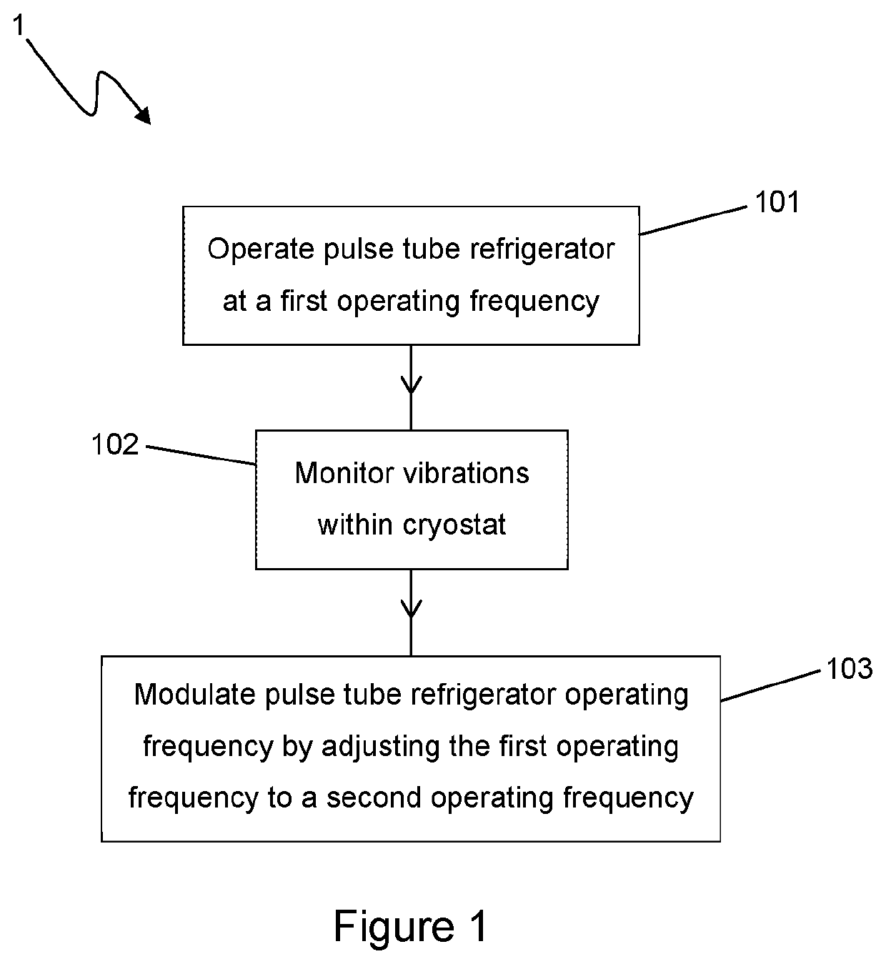
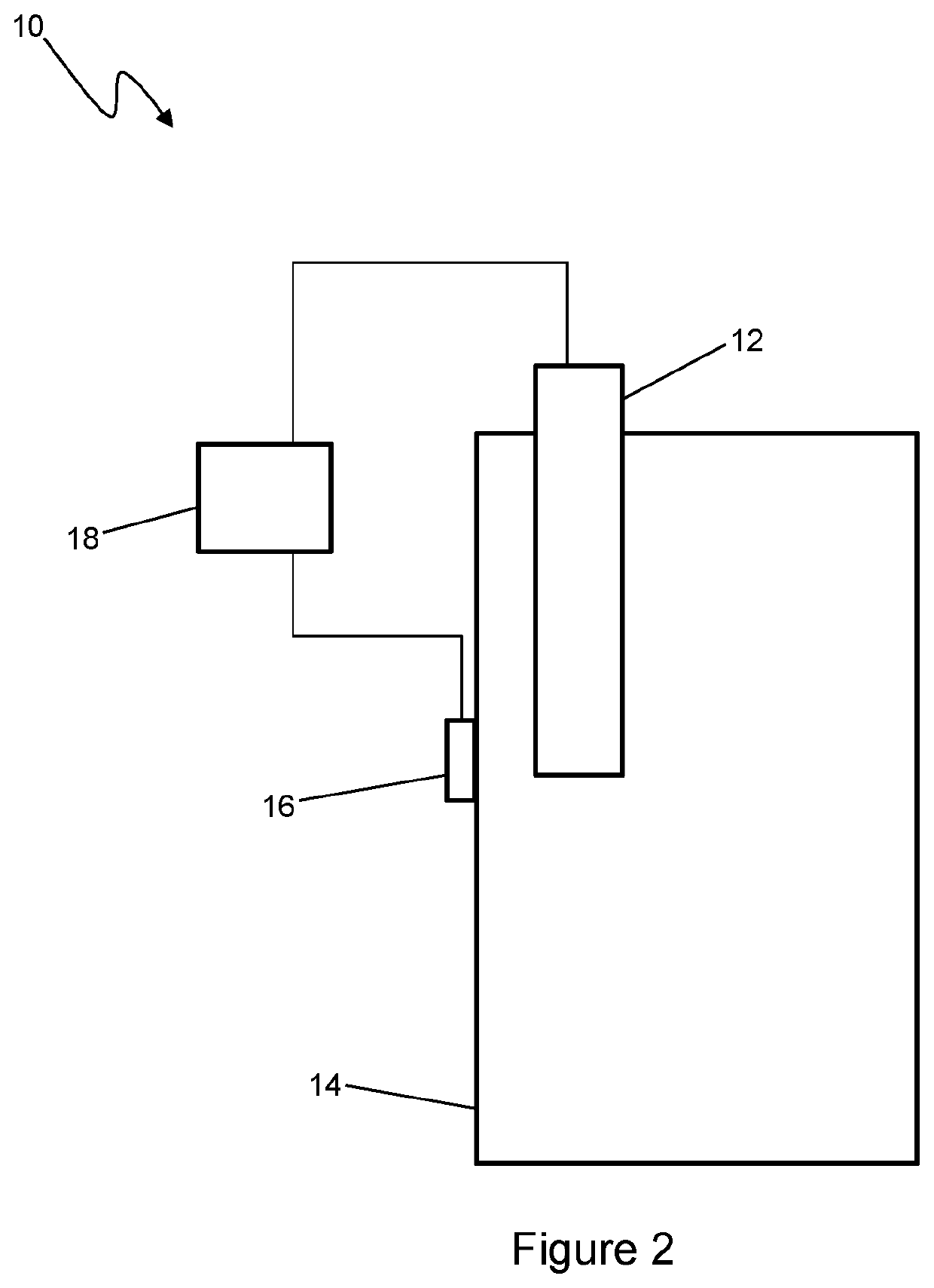
[0043]Referring now to FIG. 1 and FIG. 2, a process of a first example noise reduction method is illustrated generally at 1 in FIG. 1 and an example cryogenic cooling system is illustrated generally at 10 in FIG. 2.

[0044]In the cryogenic cooling system 10, a pulse tube refrigerator (PTR) 12 is coupled to a cryostat 14. The cryostat is typically mounted in a support frame (not shown). An accelerometer 16 is in contact with the cryostat and is connected to a controller 18 to which the accelerometer outputs data. The accelerometer and the controller make up the frequency adjuster.

[0045]At step 101, the PTR 12 is operated at a first operating frequency. This is achieved by operating a rotary valve (not shown) in the PTR at the first operating frequency. Additionally, the PTR typically has external components coupled to it. An


PUM


Abstract

There is provided a method of reducing noise in a cryogenic cooling system associated with a mechanical refrigerator forming part of said cooling system. The method comprises: monitoring vibrations in the cooling system during operation of the mechanical refrigerator; and modulating an operating frequency of the mechanical refrigerator based on the monitored vibrations so as to reduce the amplitude of said vibrations. This allows noise within the cooling system to be reduced.

Description


Claims


Application Information

Patent Timeline
Owner OXFORD INSTR NANOTECH TOOLS
Why Eureka
Try Eureka