Image forming system and wireless operation unit
- Summary
- Abstract
- Description
- Claims
- Application Information
AI Technical Summary
Problems solved by technology
Method used
Image

Examples
first embodiment
Image Forming Apparatus
[0038]Hereinafter, the overall configuration of the image forming apparatus according to first embodiment of the present invention will be described together with image forming operations with reference to the drawings. The dimensions, materials, shapes, and relative arrangements of the components described below are not intended to limit the scope of the present invention only to them unless otherwise specified.
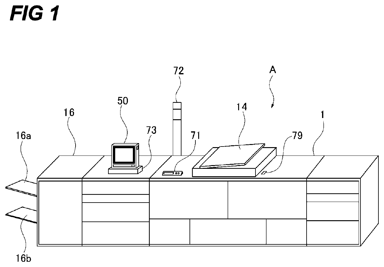
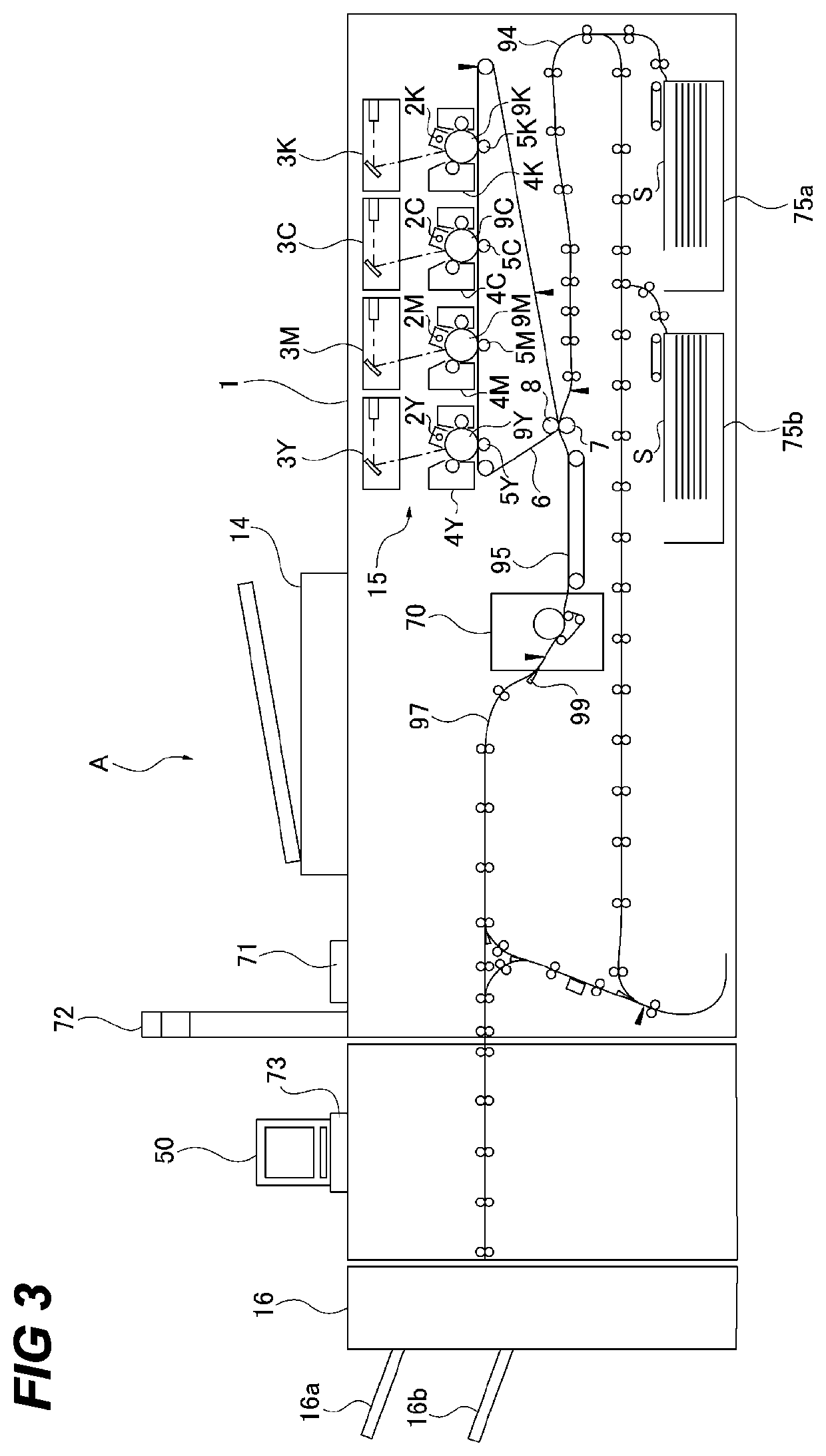
[0039]FIG. 1 is a schematic diagram showing a cross-sectional view of an image forming system A including the image forming apparatus 1. As shown in FIG. 1, the image forming system A includes an image forming apparatus 1 which forms an image on the sheet S, and the post-processing apparatus 16 which performs post-processing such as stapling, punching, and bookbinding for the sheet S on which the image has been formed by the image forming apparatus 1. At the upper portion of the image forming system 1, the reader 14 is provided which optically reads the i
second embodiment
[0087]Next, the second embodiment of the image forming apparatus will be described using figures. Only the configuration different from the first embodiment will be described and the parts of the description common with the first embodiment are omitted using the same reference symbols.
[0088]The image forming apparatus 1 of this embodiment is configured such that a part of the images to be displayed on the display 51 is stored in the ROM 22 of the remote operation unit 50. Specifically, the image data (data of the second screen image) shown in FIGS. 8A, 8B, and 10A are stored in advance in the ROM 22 of the remote operation unit 50 as images related to the image forming apparatus 1. The CPU 21 controls the display 51 such that an image to be displayed on the display 51 is switched between an image based on the image data stored in the ROM 22 (the second screen image) and an image based on the image data received by the image reception portion 93 (the first screen image). The CPU 21 may
third embodiment
[0112]Next, the third embodiment of the image forming apparatus will be described using the figures. Only the configuration different from the first and second embodiments will be described and the parts of the description common with the first and second embodiments are omitted using the same reference symbols.
[0113]In this embodiment, a single remote operation unit 50 may be used to operate each of image forming apparatuses 1 by switching a connection destination. The rest of the configuration is the same as that of the image forming apparatus 1 of the first or second embodiment. That is, the configuration of this embodiment may be applied to that of the first and second embodiments.
[0114]FIG. 14A shows the main menu screen image displayed on the display 51 of the remote operation unit 50. As shown in FIG. 14A, the main menu screen image has the destination setting button 66 for setting the image forming apparatus 1 to which the remote operation unit 50 is connected, and the destinat
PUM
 Abstract
Description
Claims
Application Information
 - R&D Engineer
- R&D Manager
- IP Professional
- Industry Leading Data Capabilities
- Powerful AI technology
- Patent DNA Extraction
Browse by: Latest US Patents, China's latest patents, Technical Efficacy Thesaurus, Application Domain, Technology Topic.
© 2024 PatSnap. All rights reserved.Legal|Privacy policy|Modern Slavery Act Transparency Statement|Sitemap