Optical sensing system

a sensing system and optical technology, applied in the field of optical systems, can solve the problems of shortening the detection range of lidar, emitted light intensity and received light intensity are not used effectively, and achieve the effect of reducing the loss of light beams and improving the utilization of light beams

Pending Publication Date: 2022-08-25
CORETRONIC
View PDF0 Cites 0 Cited by
  • Summary
  • Abstract
  • Description
  • Claims
  • Application Information

AI Technical Summary

Benefits of technology

The present technology helps improve how much it uses up its own energy by making sure that there are no lights on during certain periods or when they shouldn't be used for some purpose (such as measuring temperature).

Problems solved by technology

This patented technical problem addressed in this patents relating to Light Detection (LIDAR) systems involves improving their ability to detect small targets accurately without reducing its overall brightness level due to high levels of ambient noise caused by reflected sunlight from surrounding objects during operation.

Method used


Image

  • Optical sensing system
  • Optical sensing system

Examples


Embodiment Construction

[0013]In the following detailed description of the preferred embodiments, reference is made to the accompanying drawings which form a part hereof, and in which are shown by way of illustration specific embodiments in which the invention may be practiced. In this regard, directional terminology, such as “top,”“bottom,”“front,”“back,” etc., is used with reference to the orientation of the FIG.(s) being described. The components of the invention may be positioned in a number of different orientations. As such, the directional terminology is adapted for purposes of illustration and is in no way limiting. On the other hand, the drawings are only schematic and the sizes of components may be exaggerated for clarity. It is to be understood that other embodiments may be utilized and structural changes may be made without departing from the scope of the invention. Also, it is to be understood that the phraseology and terminology used herein are for the purpose of description and should not be re


PUM


Abstract

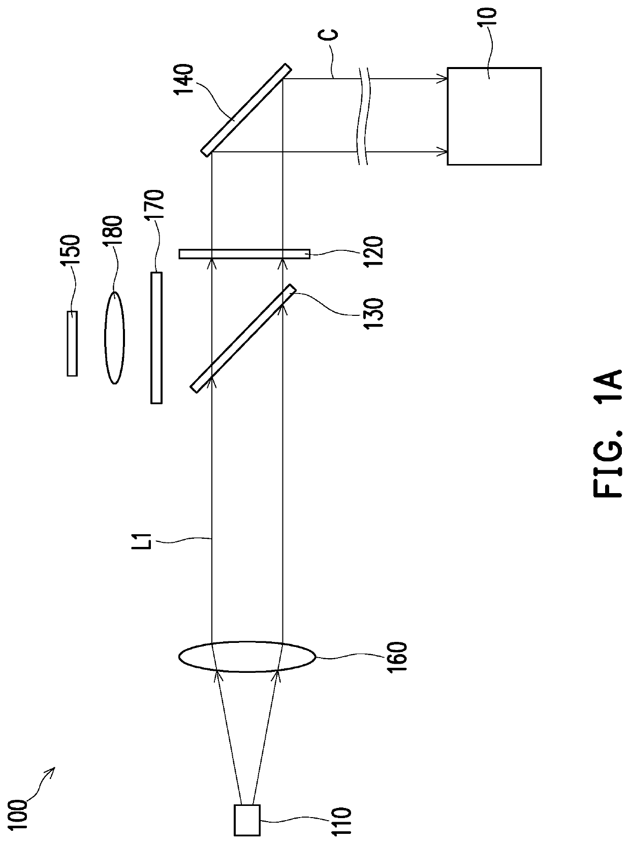
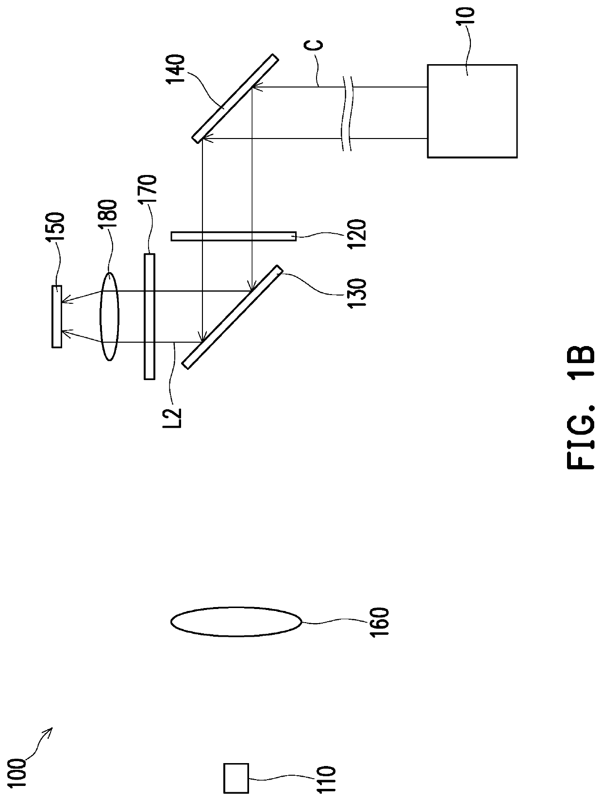
An optical sensing system for sensing a target object is provided. The optical sensing system includes a light source, an optical wave plate, a polarizing beam-splitting element, a reflecting element, and a sensing element. The light source provides a first linearly polarized light beam. The optical wave plate is adapted to convert the first linearly polarized light beam into a circularly polarized light beam and convert the circularly polarized light beam into a second linearly polarized light beam. The polarizing beam-splitting element is adapted to allow the first linearly polarized light beam to pass and reflect the second linearly polarized light beam. The reflecting element is adapted to reflect the circularly polarized light beam to the target object and to reflect the circularly polarized light beam from the target object. The sensing element is disposed on a transmission path of the second linearly polarized light beam.

Description


Claims


Application Information

Patent Timeline
Owner CORETRONIC
Why Eureka
Try Eureka