Catalytic composition and process for the alkylation and/or transalkylation of aromatic compounds
- Summary
- Abstract
- Description
- Claims
- Application Information
AI Technical Summary
Problems solved by technology
Method used
Image

Examples
example 2
The humid panel obtained in example 1 is dried in an oven for 1 hour at 150.degree. C., and calcined in muffle for 5 hours at 550.degree. C. in a stream of air.
The calcined solid is dispersed in an aqueous solution of ammonium acetate (150 g of water and 8 g of ammonium acetate) for the ion exchange. The suspension is heated under stirring for an hour at about 80.degree. C.
The suspension is then filtered and the solid obtained is redispersed in demineralized water (150 ml) for the washing. The suspension is then refiltered and the ion exchange and washing are repeated in sequence. The solid is then washed again and refiltered and then dried in an oven for 1 hour at 150.degree. C. thus obtaining the zeolite whose cationic sites are ammonium and alkylammonium ions. This zeolite is calcined in muffle for 5 hours at 550.degree. C. in a stream of air thus obtaining the beta zeolite in acid form. Upon elemental analysis, the sodium residue in the latter sample is in fact equal to 106 ppm. Th
example 3
The humid panel obtained in example 1 is redispersed in an aqueous solution of ammonium acetate (200 g of water and 16 g of ammonium acetate) for the ion exchange. This suspension is heated under stirring for an hour at about 80.degree. C.
The suspension is then filtered and the solid obtained is redispersed in demineralized water (150 cc) for the washing. The suspension is then refiltered and a humid panel of beta zeolite is again obtained in whose cationic sites are ammonium and alkylammonium ions.
Upon elemental analysis, the sodium residue in the latter sample is in fact equal to 112 ppm. The content of aluminum is equal to 3.38% [Al] / [Na]=257).
The product was characterized by X-ray diffraction from powders.
example 4
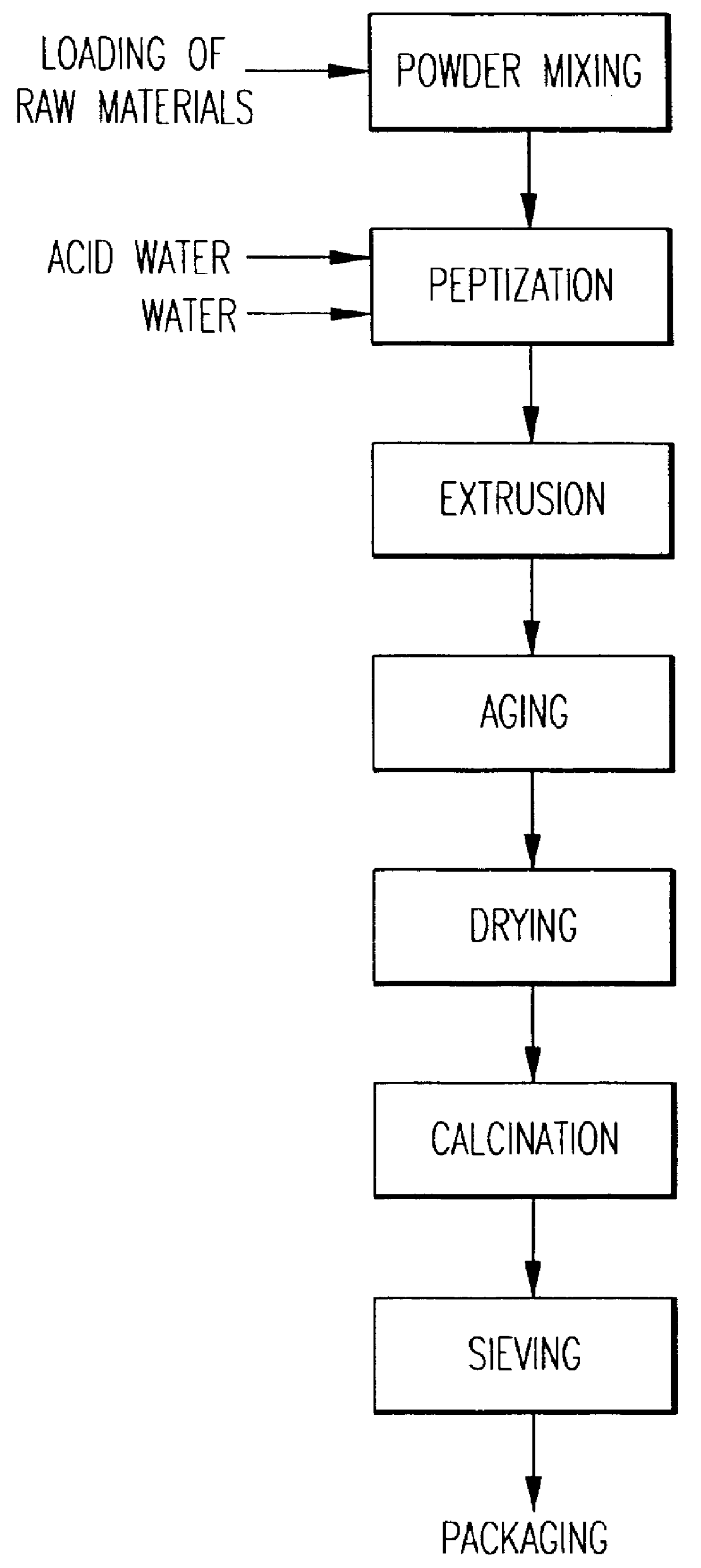
A catalyst is prepared called CATALYST A1 based on beta zeolite prepared according to example 3 and alumina in the form of bohemite, according to an extrusion process whose main parameters adopted are indicated in table I.
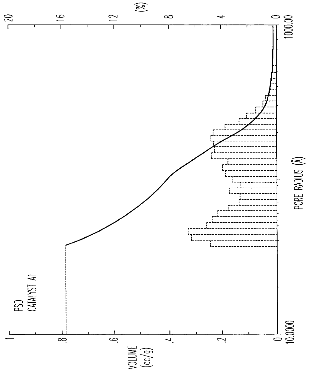
The beta zeolite used for this preparation was not subjected to any calcination treatment. The preparation procedure is schematized in the flowsheet of FIG. 1. The catalyst thus obtained was then subjected to a single calcination treatment in air. Table I shows the ranges of porosity of the catalyst from which it can be observed that the fraction of pores with radius >100 .ANG. is more than 35% in accordance with what is claimed in EP 687500, whereas the total volume of EPV extrazeolitic pores is equal to 0.81 ml / g.
FIG. 2 shows the graph of the extrazeolitic PSD relating to catalyst A1, to be compared with the volume of micropores, i.e. essentially zeolitic pores, equal to 0.12 ml / g.
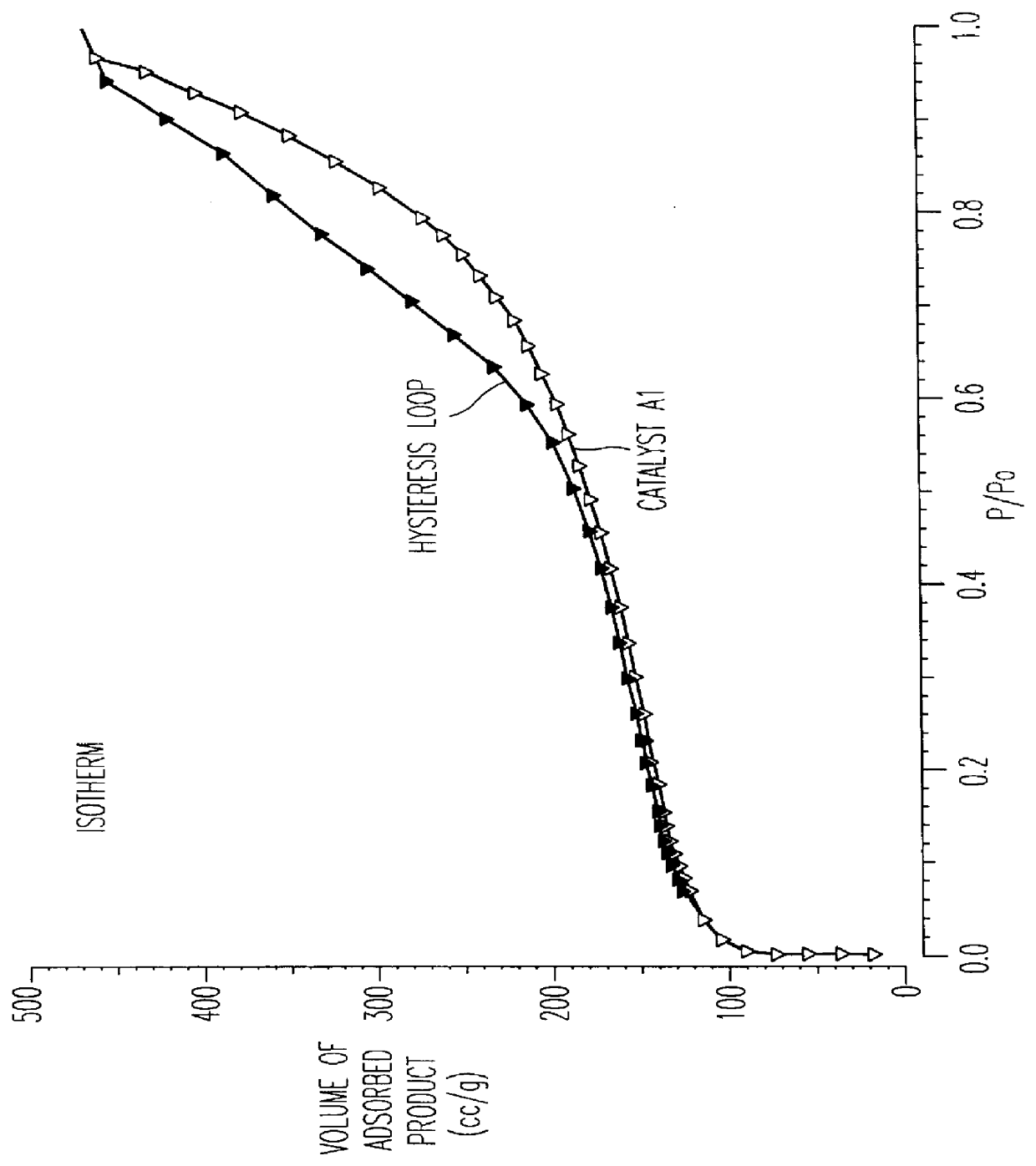
FIG. 3 shows the complete absorption isotherm with nitrogen at the temperature of
PUM
| Property | Measurement | Unit |
|---|---|---|
| Fraction | aaaaa | aaaaa |
| Fraction | aaaaa | aaaaa |
| Time | aaaaa | aaaaa |
Abstract
Description
Claims
Application Information
 - R&D Engineer
- R&D Manager
- IP Professional
- Industry Leading Data Capabilities
- Powerful AI technology
- Patent DNA Extraction
Browse by: Latest US Patents, China's latest patents, Technical Efficacy Thesaurus, Application Domain, Technology Topic.
© 2024 PatSnap. All rights reserved.Legal|Privacy policy|Modern Slavery Act Transparency Statement|Sitemap