Device for micromechanical switching of signals

a micromechanical and signal technology, applied in the direction of thermal micromechanical switches, thermal switch details, contacts, etc., can solve the problems of large losses, high energy consumption, and procedure wear on the free ends of arms and contact surfaces, and achieve the effect of low power consumption

Inactive Publication Date: 2002-09-24
IMEGO
View PDF13 Cites 18 Cited by
  • Summary
  • Abstract
  • Description
  • Claims
  • Application Information

AI Technical Summary

Benefits of technology

The technical effect of this patented technology is that it provides an efficient way for electronic devices with memristors or other components where they are turned off during use without consuming too much energy when needed again (a phenomenon called shutdown).

Problems solved by technology

The technical problem addressed in this patents relating to microelectronic devices called “MEMs” is how to reduce power dissage while still providing precise control over electrical connections within electronic systems like communication networks. Existing solutions involve bulky motions involving moving contacts, leading to increased wear and tear resistance compared to smaller spring structures. Therefore there needs to develop a new type of switch design that allows for efficient production and reduced complexity.

Method used


Image

  • Device for micromechanical switching of signals
  • Device for micromechanical switching of signals
  • Device for micromechanical switching of signals

Examples


Embodiment Construction

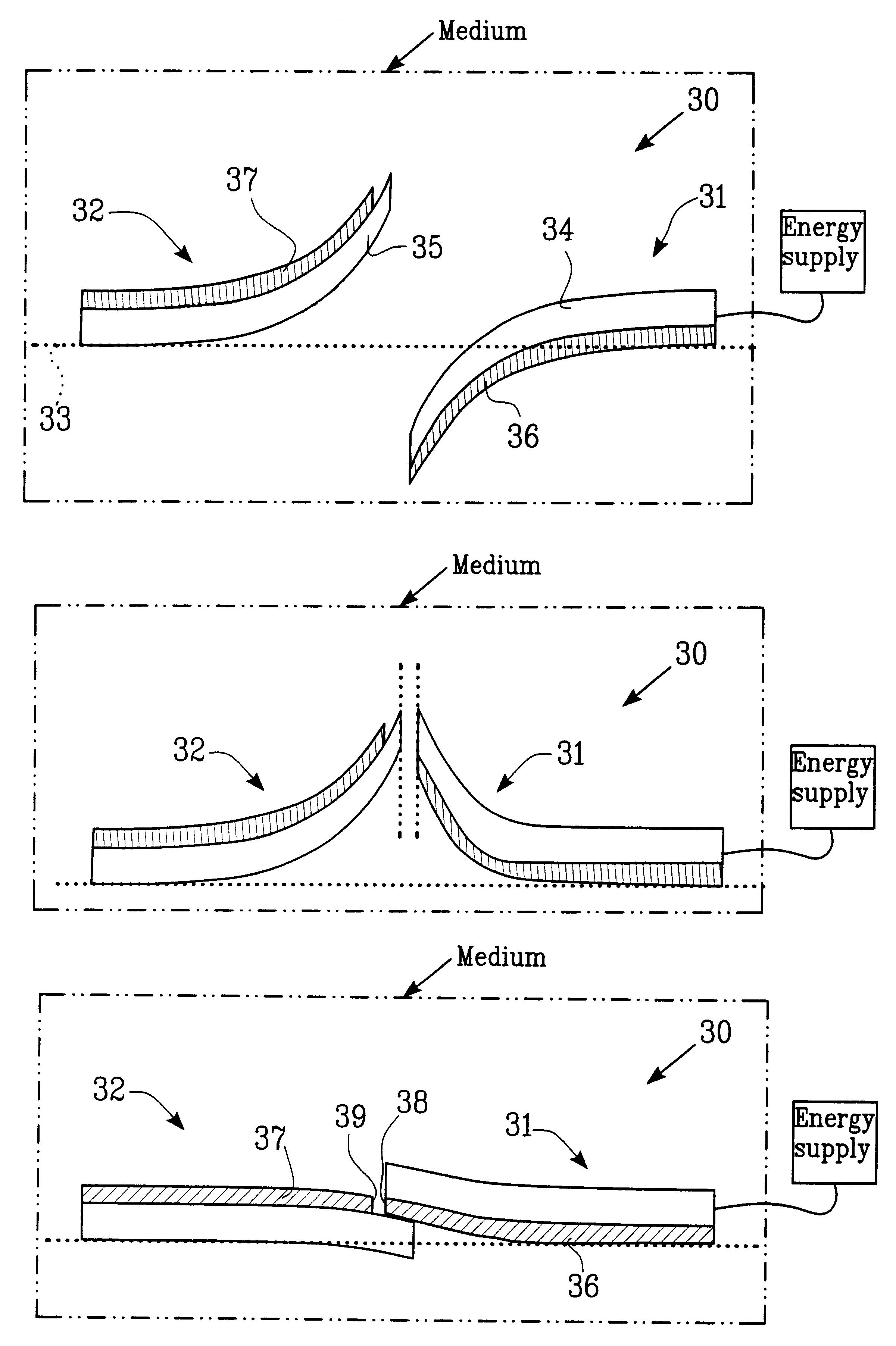
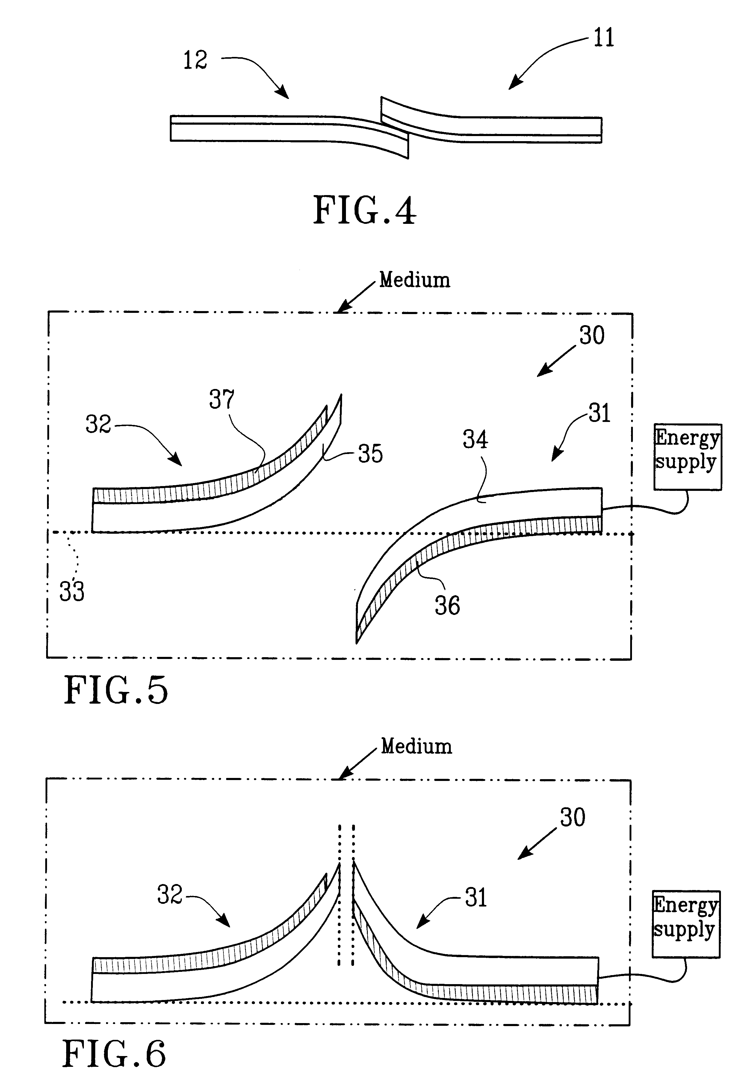
A device according to the invention includes at least two movable elements, realized as arms, which through thermal actuation can close and open a circuit. Suitable material combinations will be chosen so that two resisting switching arms deflect in different directions, for example one of them deflects upwards while the other one deflects downwards at the intended operating temperature and that arms can be arranged to deflect in opposite directions through heating. Moreover, the arms are arranged so that they essentially overlap each other in the position where they should interlock or contact, for example when both arms are straightened and at least one of them through heating could deflect so much that it can be constrained to pass the other arm.

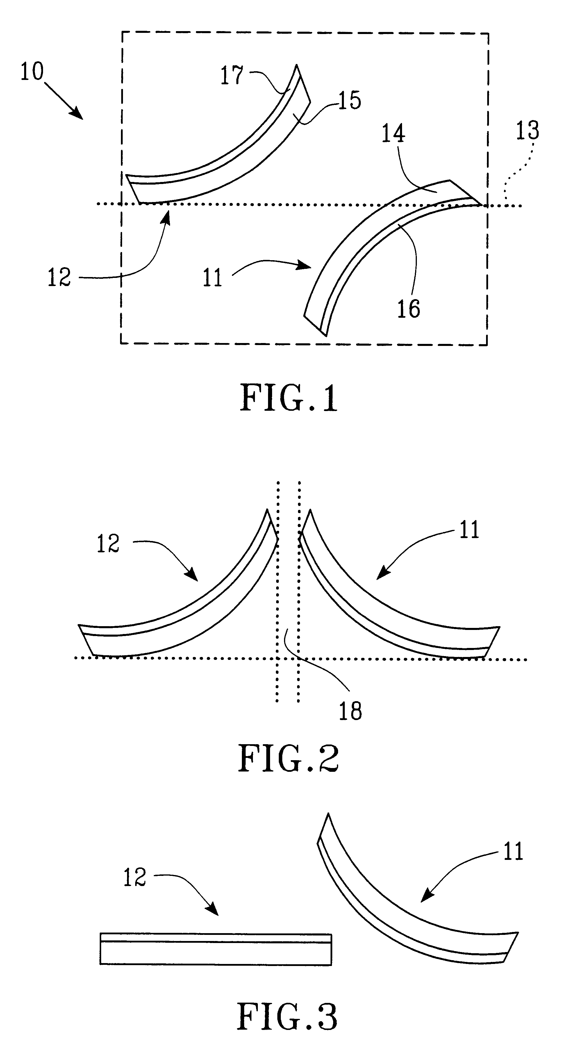
A bistable micromechanical switch 10 is shown in FIG. 1 in an open state and it includes a first and a second switching arm 11 and 12, respectively, provided on or in a conveyer or a substrate (shown with broken and dotted line), for example


PUM


Abstract

The invention refers to a micromechanical switching device including at least two contact elements (11, 12, 31, 32), which are provided at least partly movable relative each other and via thermal actuation can be closed and opened, whereby the contact elements (11, 12, 31, 32) at least partly are comprised of at least two materials (14, 15, 16, 17, 34-37) with essentially different thermal expansion coefficients. The contact elements (11, 12, 31, 32) at excitation are arranged to displace essentially in same level and in different directions.

Description


Claims


Application Information

Patent Timeline
Owner IMEGO
Why Eureka
Try Eureka