High-resolution, all-reflective imaging spectrometer

a spectrometer and all-reflective technology, applied in the field of high-resolution all-reflective imaging spectrometers, can solve the problems of limiting the usefulness of the results for some applications, lateral viewing range, and relatively narrow field of view, so as to reduce the magnitude of the “spectral smile” or eliminate the

Inactive Publication Date: 2005-05-03
RAYTHEON CO
View PDF14 Cites 34 Cited by
  • Summary
  • Abstract
  • Description
  • Claims
  • Application Information

AI Technical Summary

Benefits of technology

The invention improves upon previous methods by reducing or eliminating certain features that were previously present. This results in improved performance and efficiency.

Problems solved by technology

This patent describes improving the performance of existing imaging spectrometers that require refractive lenses due to their limited fields of view. However, these improvements can be affected by temperature changes and radiation affecting the quality of the resulting data.

Method used


Image

  • High-resolution, all-reflective imaging spectrometer
  • High-resolution, all-reflective imaging spectrometer
  • High-resolution, all-reflective imaging spectrometer

Examples


Embodiment Construction

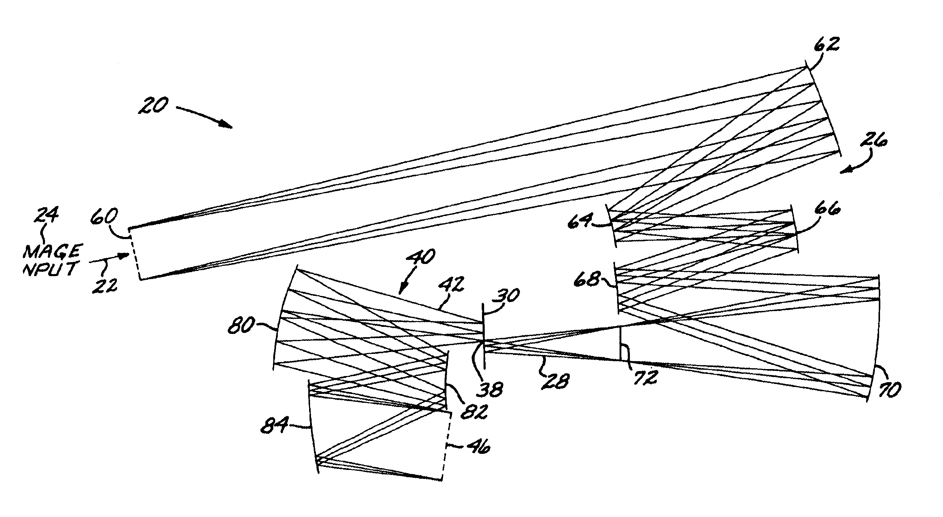
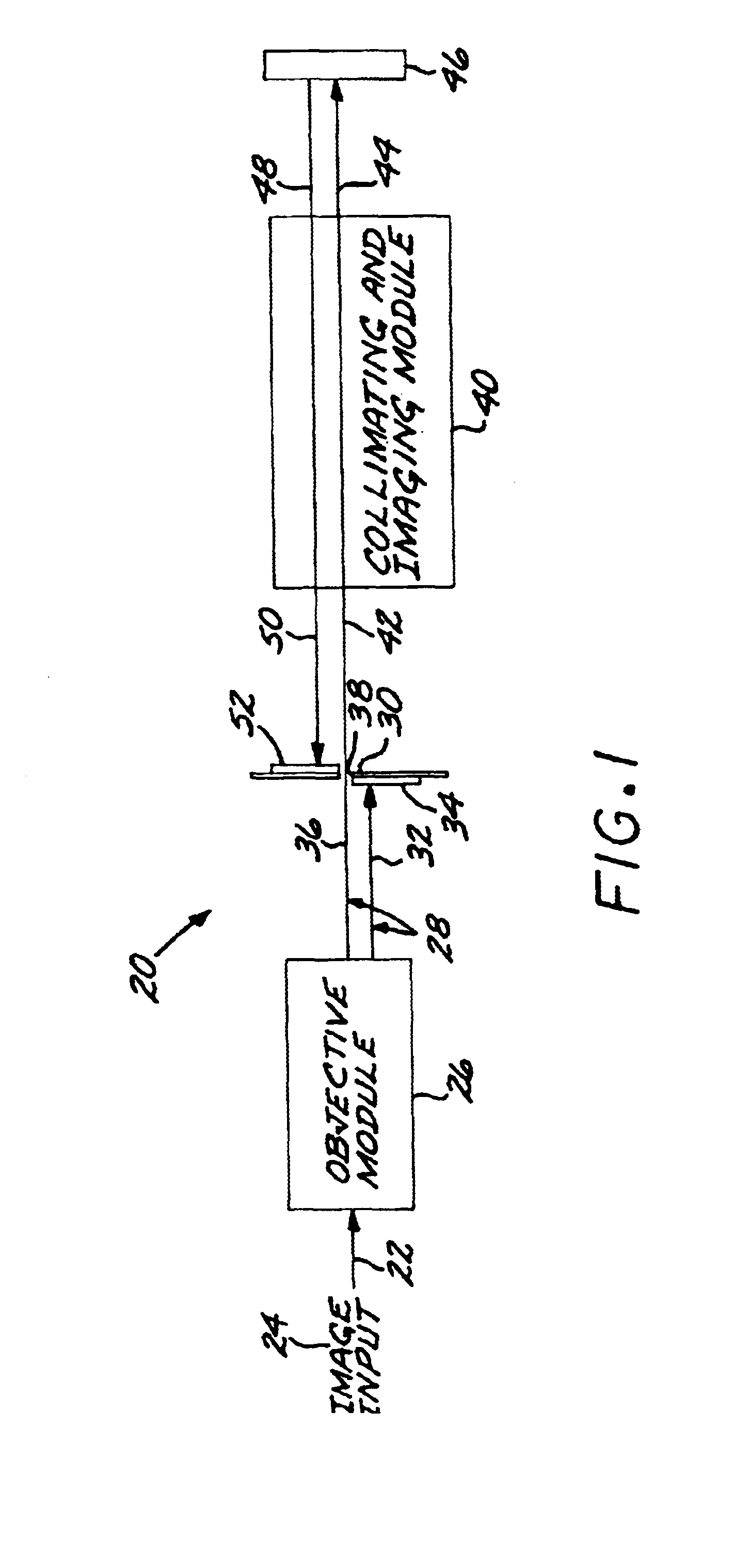
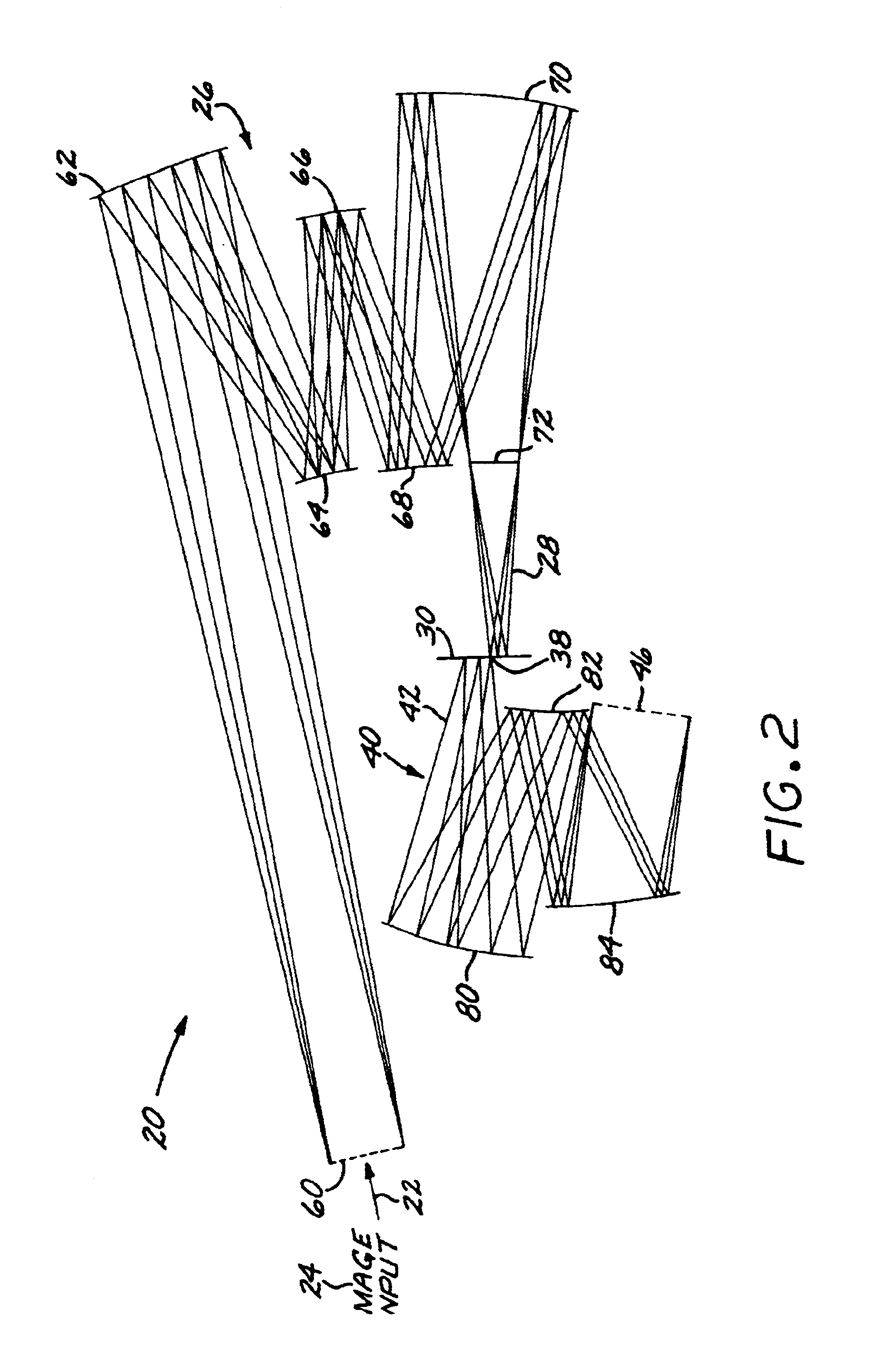
[0028]FIG. 1 schematically depicts in general form an imaging spectrometer 20 comprising an all-reflective imaging spectrometer optical system. Light energy 22 from an image input 24 of a viewed scene enters an all-reflective objective module 26, which serves as the foreoptics of the imaging spectrometer 20. (As used herein, “all-reflective” means that the optical module or element contains only reflective optical elements such as mirrors in the optical path, and no powered refractive optical elements such as lenses in the optical path.) The objective module 26 produces an objective module output 28 that is directed to an image plane 30, which is preferably flat. A first portion 32 of the objective module output 28 is incident upon a panchromatic imaging detector 34, which is also preferably flat, located at the image plane 30 and facing the objective module 26. A second portion 36 of the objective module output 28 passes through an exit slit 38 located at the image plane 30. The secon


PUM


Abstract

An imaging spectrometer includes an all-reflective objective module that receives an image input and produces an objective module output at an exit slit, and an all-reflective collimating-and-imaging module that receives the objective module output as an objective-end input and produces a collimating-end output, wherein the collimating-and-imaging module comprises a reflective triplet. A dispersive element receives the collimating-end output and produces a dispersive-end input into the collimating-and-imaging module that is reflected through the collimating-and-imaging module to produce a spectral-image-end output. An imaging detector receives the spectral-image-end output of the collimating-and-imaging module. The objective module may be a three-mirror anastigmat having an integral corrector mirror therein, or an all-reflective, relayed optical system comprising a set of five powered mirrors whose powers sum to substantially zero. The collimating-and-imaging module may be optimized to minimize spectral smile.

Description


Claims


Application Information

Patent Timeline
Owner RAYTHEON CO
Why Eureka
Try Eureka