Ink cartridge for ink jet recording device
a technology of ink jet recording device and ink cartridge, which is applied in printing and other directions, can solve the problems of increasing the number of nozzle openings of the recording head, increasing the amount of ink consumed per unit time, and increasing the water head, so as to increase the effective usable ink storage amount without degrading the print quality, and easily change the amount of ink storage.
- Summary
- Abstract
- Description
- Claims
- Application Information
AI Technical Summary
Benefits of technology
Problems solved by technology
Method used
Image

Examples
first embodiment
[0072
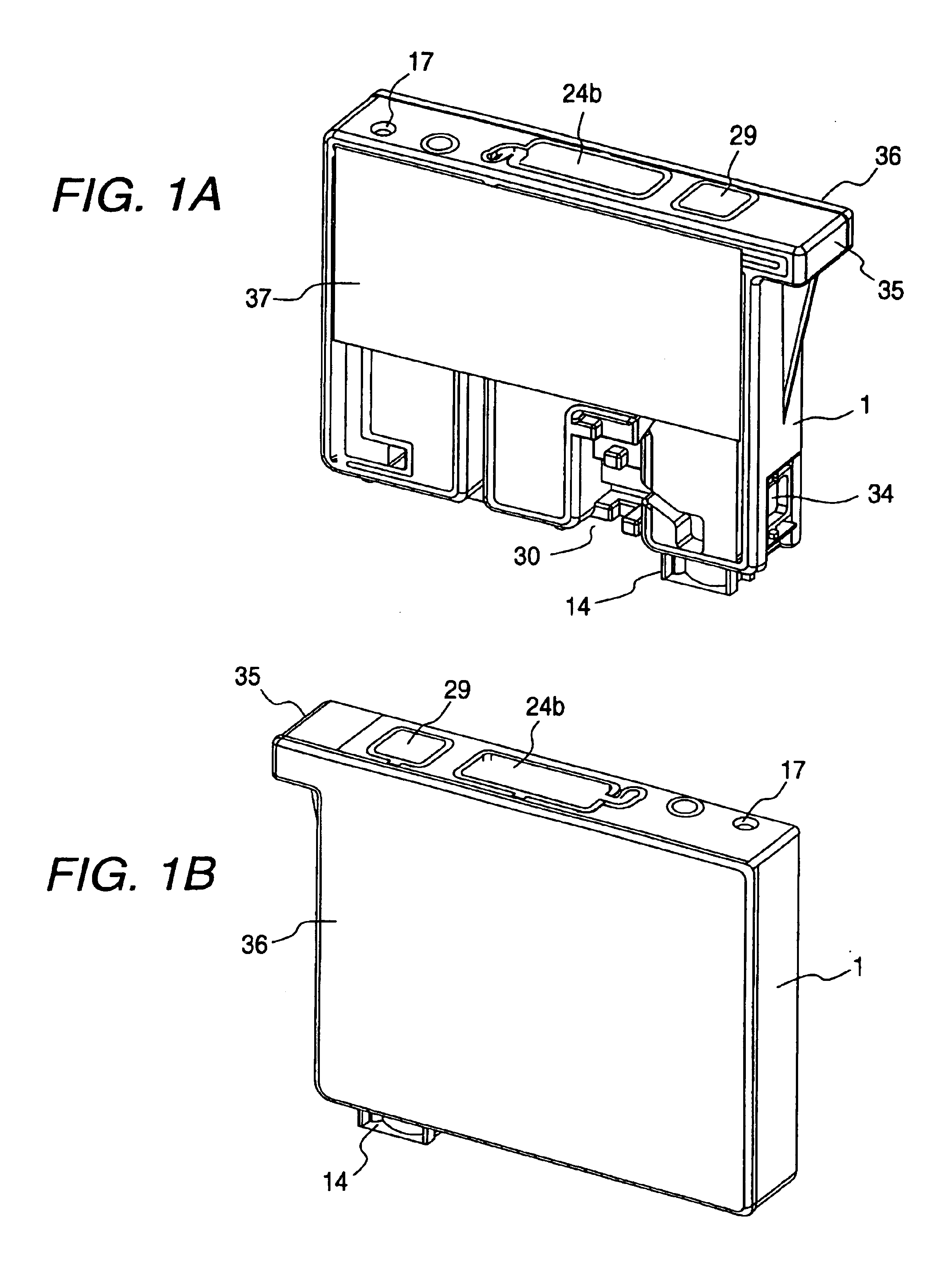
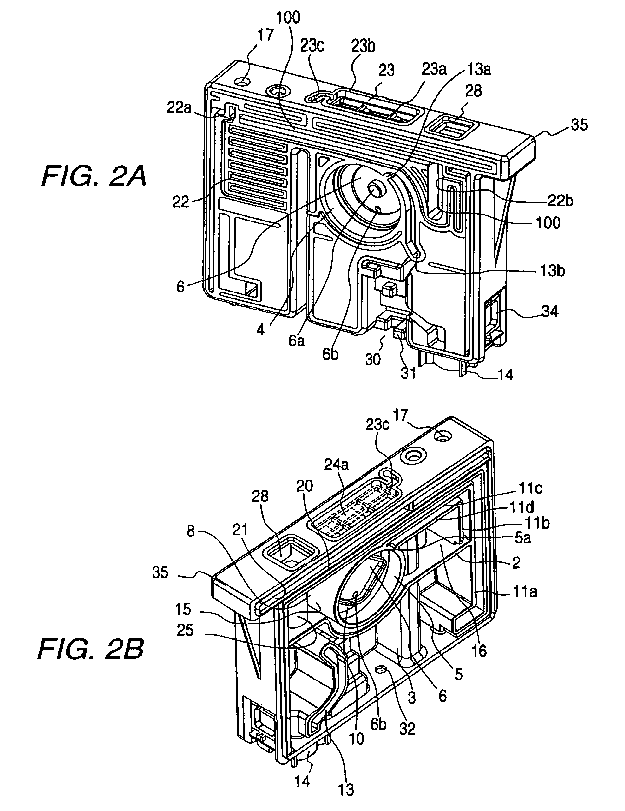
[0073]FIGS. 1A, 1B, 2A and 2B show the front and rear structures of a container body 1 forming an ink cartridge, which constitutes a first embodiment of the present invention. FIG. 3 shows the bottom structure of the container body 1. The interior of the container body 1 is vertically divided by a wall 2, extending substantially horizontally, into a lower section region and an upper section region. In the lower section region, a first ink chamber 3 serving as a lower section ink chamber is formed in a lower section region. In the upper section region, there are formed: a differential pressure valve storage chamber 4, serving as a negative pressure generating mechanism to be described later; a filter chamber 5 for storing a filter; and a second ink chamber 8 serving as an upper section ink chamber and including first and second ink storage portions 15 and 16.
[0074]The differential pressure valve storage chamber 4 and the filter chamber 5 are partitioned one from the other by a wall
second embodiment
[0100
[0101]FIGS. 12A and 12B show an external appearance of an ink cartridge which constitutes a second exemplary embodiment of the present invention. The ink cartridge 61 is mainly constructed of a flat, rectangular container body 62 whose one side is opened, and a cover member 63 for sealingly closing the opening. The container body 62 is integrally formed with an ink supply port 64 at the forward end thereof as viewed in the cartridge insertion direction (the lower end in this embodiment), and retaining members 65 and 66 at the corners of the upper part thereof. A memory device 67 is provided under the retaining member 65, which is located on the ink supply port (64) side. A valve storage chamber 68 is provided under the other retaining member 66. A valve member (not shown) is stored in the ink supply port 64 so as to be opened when an ink supply needle is inserted into the ink supply port 64.
[0102]FIGS. 13 and 14 show an example of a flow passage formed in the container body 62 of
third embodiment
[0150
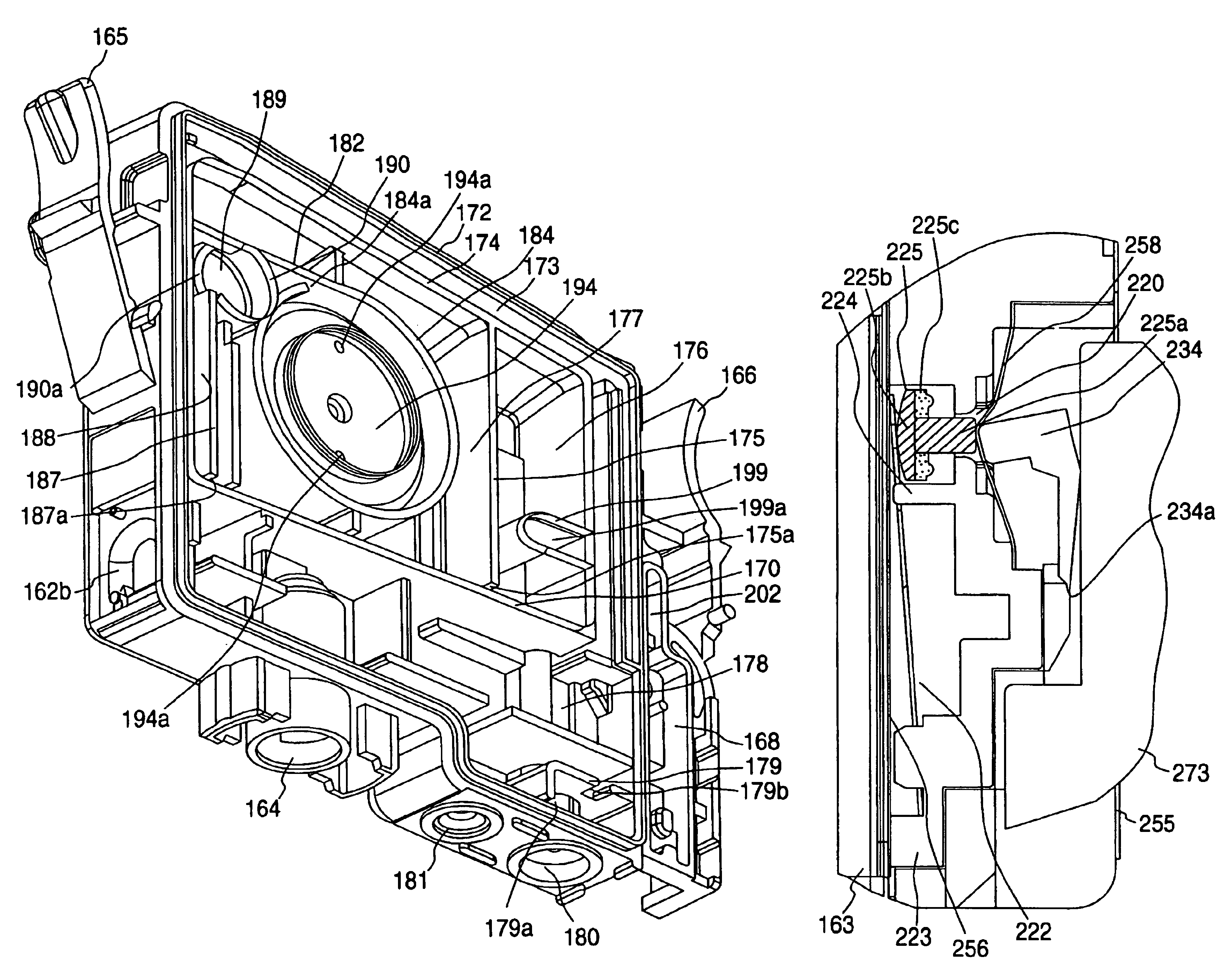
[0151]FIGS. 22A, 22B and 23A to 23D show an external appearance of another example of the ink cartridge according to the present invention, which constitutes a third exemplary embodiment. The ink cartridge 161 is mainly constructed of a flat, rectangular, box-like container body 162, one surface of which is open and the other opposite surface is closed, and a cover member 163 for closing the opening of the container body 162. An ink supply port 164 is formed at a longitudinally offset position in the leading end side of the insertion direction, i.e. in the bottom surface in this embodiment. Retaining members 165 and 166 are formed integrally with the container body 162 at upper lateral portions.
[0152]The retaining member 165 located closer to the ink supply port 164 has, a rotation fulcrum 165a located slightly above the leading end side of the retaining member 165 in the insertion direction, i.e. the lower end of the retaining member 165 in this embodiment, so that the upper port
PUM
 Abstract
Description
Claims
Application Information
 - R&D Engineer
- R&D Manager
- IP Professional
- Industry Leading Data Capabilities
- Powerful AI technology
- Patent DNA Extraction
Browse by: Latest US Patents, China's latest patents, Technical Efficacy Thesaurus, Application Domain, Technology Topic.
© 2024 PatSnap. All rights reserved.Legal|Privacy policy|Modern Slavery Act Transparency Statement|Sitemap