Digital imaging system
a digital imaging and system technology, applied in the field of digital cameras, can solve the problems of troublesome printing of pictures, troublesome sorting of printed pictures for each order, and inability to achieve high-quality printing in which the proper performance of dsc is exerted, and achieve the effect of facilitating the sorting of pictures after the prin
- Summary
- Abstract
- Description
- Claims
- Application Information
AI Technical Summary
Benefits of technology
Problems solved by technology
Method used
Image

Examples
first exemplary embodiment
[0091]A digital camera print system according to a first embodiment of the present invention is described with reference to FIGS. 1–7. Each of the components is constituted of hardware or firmware, or both.
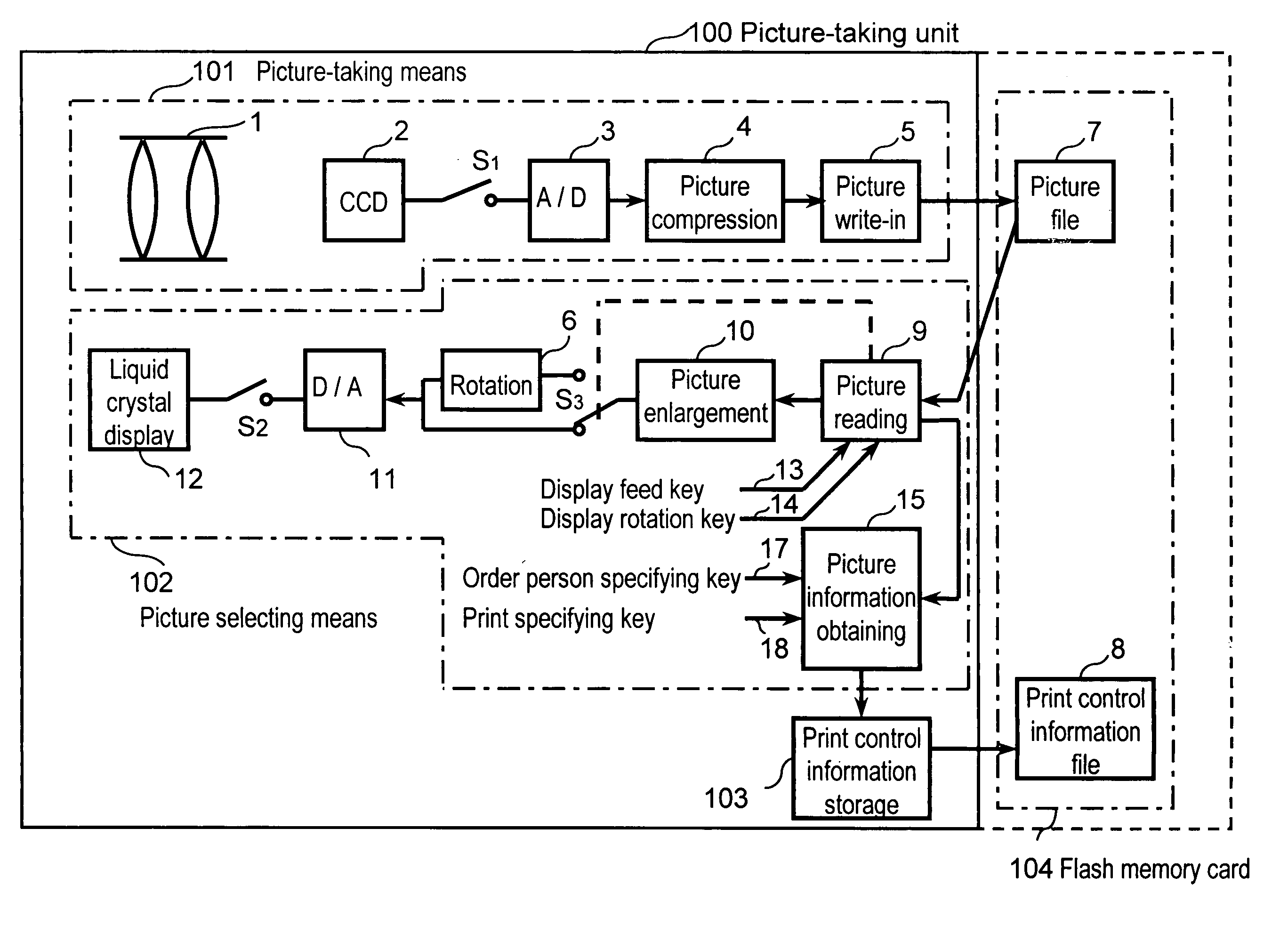
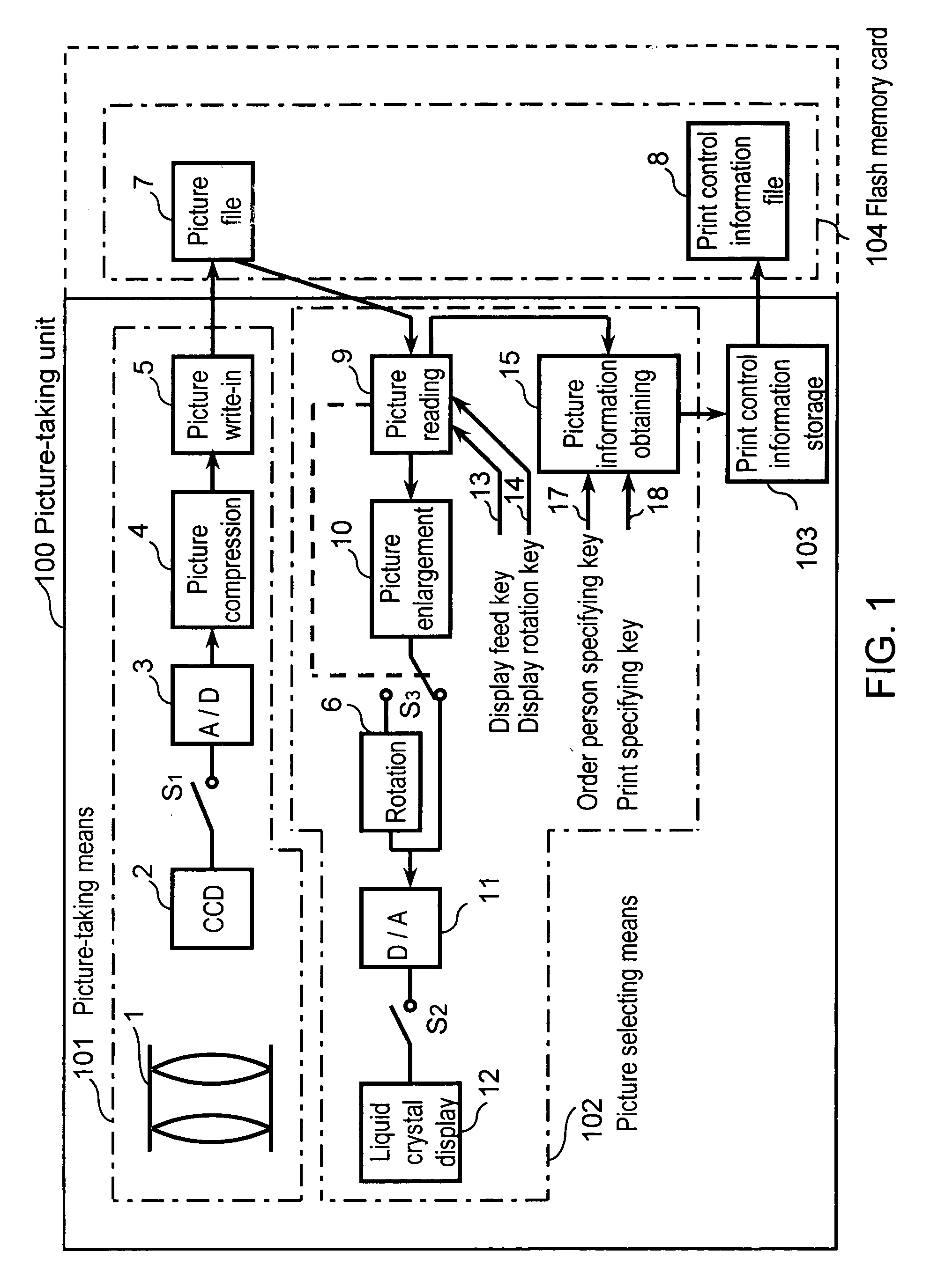
[0092]A digital still camera 100, which is a picture-taking unit constituting a digital camera print system according to a first embodiment of the present invention, is described with reference to a block diagram of FIG. 1. The picture-taking unit 100 comprises picture-taking means 101, picture selecting means 102, print control information storage means 103 and a flash memory card 104.
[0093]In the picture-taking means 101 of FIG. 1, an objective lens 1 focuses an optical image of an object on a charge coupled device (hereinafter referred to as CCD) 2. A signal output of the CCD 2 by this optical image is fetched through a switch (shutter button) S1 which is a shutter and input to an A / D converter 3, so that the analog signal is converted to a digital signal. The digital output of
second exemplary embodiment
[0123]A picture processing system utilizing the digital camera according to a second embodiment of the present invention is described with reference to FIGS. 8A–8C.
[0124]For this embodiment, a case in which a printer unit 200a carries out double zoom print without any treatment by specifying double zoom processing in a picture-taking unit 100a upon print operation, is described.
[0125]Referring to FIG. 8A, a digital still camera which is a picture-taking unit comprises a picture-taking means 101a, a picture selecting means 102a, a processing control information storage means 103a and a flash memory card 104a. Because the picture-taking unit 100a has the same structure as the picture-taking unit 100 of the first embodiment in FIG. 1, a detailed description is omitted. Like the first embodiment, if a user selects that he wants to print in double enlargement from picture data stored in the picture file 7 by using a picture selecting means 102a of the picture-taking unit 100a, the processin
third exemplary embodiment
[0127]A display system utilizing a digital camera according to a third embodiment of the present invention is described with reference to FIGS. 9 and 10.
[0128]Referring to FIG. 9, a digital still camera 100b which is a picture-taking unit comprises a picture-taking means 101b, a display picture selecting means 102b, a display control information storage means 103b and a flash memory card 104b. Because the picture-taking unit 100b is of the same structure as the picture-taking unit 100 of the first exemplary embodiment in FIG. 1, a detailed description is omitted.
[0129]According to this embodiment, like the print system of FIG. 8, in a picture-taking unit 100b of this display system, a display control information storage means 103b produces a file name of a picture selected by a display picture selecting means 102b of the digital camera by user on a flash memory card 104b as a display control information file 8b (FIG. 4B shows an example of the file 8b).
[0130]As shown in FIG. 10, a disp
PUM
 Abstract
Description
Claims
Application Information
 - R&D Engineer
- R&D Manager
- IP Professional
- Industry Leading Data Capabilities
- Powerful AI technology
- Patent DNA Extraction
Browse by: Latest US Patents, China's latest patents, Technical Efficacy Thesaurus, Application Domain, Technology Topic.
© 2024 PatSnap. All rights reserved.Legal|Privacy policy|Modern Slavery Act Transparency Statement|Sitemap