Image forming apparatus and fixing temperature control method for the apparatus

Inactive Publication Date: 2006-02-21
SEIKO EPSON CORP
View PDF9 Cites 6 Cited by
  • Summary
  • Abstract
  • Description
  • Claims
  • Application Information

AI Technical Summary

Benefits of technology

[0011]A first object of the invention is to provide a control to stabilize the fixing temperature of the image forming apparatus for accomplishing the good fixing performance. A second object of the invention is to provide an image forming apparatus adapted to achieve the good fixing performance by providing the control to stabilize the fixing temperature, the image forming apparatus which transfers, to the recording medium, the color toner image formed on the intermediate transfer medium such as the intermediate transfer belt and then, fixes the color toner image to the recording medium by heating the toner, carried on the recording medium as forming the color toner image, by means of heating means.
[0012]For

Problems solved by technology

However, the reduction of the heat capacity of the heating roller entails a problem that the heating roller suffers relatively greater fluctuations of its temperature.
Particularly when a recording medium at a low temperature (about room temperatures) is fed into the fixing device, the heating roller of the small heat capacity encounters an abrupt temperature drop.
Consequently, image defects such as fixing failure and density variations may be produced, or the recording medium may be degraded due to overheating.
That is, the fixing device may fail to achieve the good fixing performance.
The abutment may interfere with the rotary transportation by the intermediate transfer belt, or cause elastic elongation of t

Method used


Image

  • Image forming apparatus and fixing temperature control method for the apparatus
  • Image forming apparatus and fixing temperature control method for the apparatus
  • Image forming apparatus and fixing temperature control method for the apparatus

Examples


first embodiment

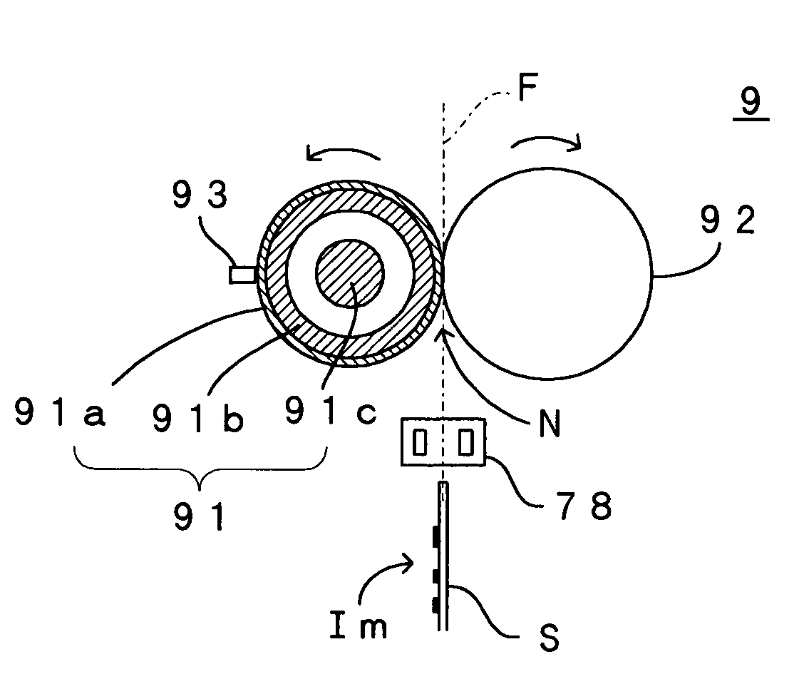
[0069]Hence, the embodiment defines the start timing of energization of the heater 91c such that, as shown in FIG. 7A, when the shift of the output signal from the pre-fixing sensor 78 is detected, a constant time period Δt2 is provided between the detection of the signal shift and the start of energization of the heater 91c. Similarly to the apparatus of the first embodiment, this arrangement ensures that a time difference t4 between the start of energization of the heater 91c and the actual arrival of the sheet S at the nip N is constant. Hence, the temperature of the heating roller 91 during the passage of the sheet S through the nip N can be maintained in the predetermined range. As a result, the heating roller 91 is maintained at the optimum temperature during the fixing operation and the good fixing performance can be achieved.

[0070]Where the output signal from the pre-fixing sensor 78 is retained at H-level, the temperature control may be carried out based on the constant contro

third embodiment

[0077]According to the temperature control operation thus arranged, as well, the same working effects as those offered by the apparatus of the third embodiment can be attained. That is, the energization of the heater 91c is started a given time period t7 earlier than the time t0 when the sheet S arrives at the nip N, whereby the temperature is stably maintained during the passage of the sheet S through the nip N.

[0078]Given the same length of period Ts of the vertical synchronous signal Vsync, such a temperature control operation has a longer control time period Tc than that of the operation of the third embodiment. Hence, the control operation is less suited for coping with fine temperature fluctuations. However, the operation reduces the load on the CPU 101 because of a lower frequency of the processings. Accordingly, such a control method is favorable in a case where, for example, the heating roller 91 has a relatively great heat capacity so that the roller is slow to be raised in t

fifth embodiment

[0082]Next, description is made on the invention which is suited for a case where the repetition period of the vertical synchronous signal Vsync is varied. In such a case, the temperature control method on assumption that the vertical synchronous signal Vsync has the constant period does not naturally hold.

[0083]FIGS. 11A and 11B are charts each representing a relation between the timing of energizing the heating roller and the temperature fluctuations on assumption that the control period is constant. In a state where the color image formation is not carried out so that the sheet S is not present in the nip N, it is relatively easy to maintain the temperature at a constant level because the heater 91c substantially presents a constant heat load. As shown in FIG. 11A, therefore, the temperature of the heating roller 91 can be maintained in the predetermined range by sensing the surface temperature of the heating roller 91 per constant control period Tc; comparing the sensed temperature


PUM


Abstract

A temperature control operation for a fixing device is performed based on a vertical synchronous signal Vsync periodically outputted in association with a cycling motion of an intermediate transfer belt. Furthermore, the temperature control operation provides a constant time difference Δt1 between a leading edge of the vertical synchronous signal Vsync and a start of energization of a heater. Therefore, a period of the vertical synchronous signal Vsync coincides with a period of the temperature control operation corresponding to each vertical synchronous signal Vsync. In addition, a constant time period is provided between the start of energization and an actual arrival of a recording medium at a nip and hence, the temperature of a heating roller can be maintained at an optimum level during the passage of the recording medium through the nip.

Description


Claims


Application Information

Patent Timeline
Owner SEIKO EPSON CORP
Why Eureka
Try Eureka