Vehicle braking system with proportional poppet valve pressure control strategy

Inactive Publication Date: 2007-05-01
KELSEY HAYES CO
View PDF23 Cites 1 Cited by
  • Summary
  • Abstract
  • Description
  • Claims
  • Application Information

AI Technical Summary

Benefits of technology

[0011]This invention relates to electrohydraulic braking (EHB) systems for vehicles and in particular to a method (algorithm) for controlling the pressure of brake fluid applied to the wheel brakes thereof. The algorithm interprets a braking pressure command input from any of a variety of braking functions, and controls the electromagnetic poppet valves to achieve the commanded pressure at a vehicle's brakes reliably and with good control in all states of flow (leakage or bulk) through the valves. Additionally, the pressure control system accepts inputs from advanced braking functions, such as ABS, VSC, TC, DRP, ACC, etc. More specifically, the purpose of the pressure control system is to provide adequate wheel pressure control with respect to dynamic response, tracking error, robustness and stability objectives, while taking into account issues such as vibration, noise and flow consumption. The pressure control system is intended for use with base braking functions, such as that described in U.S. Pat. No. 6,226,586, granted May 1, 2001, the disclosure of which is incorporated herein by reference.
[0012]The EHB pressure control system receives a desired wheel pressure command, and with a caliper pressure feedback signal, computes one voltage command for the apply valve and another one for the dump valve, both corresponding to a requested flow from the hydraulics. The voltage command drives current control electronics. The electronics in turn selectively power the apply and dump poppet valves to control flow in or out of the brakes and modulate wheel pressure as required.

Problems solved by technology

A major difference between poppet valves (used herein) and spool valves is that there is significant amount of leakage associated with poppet valves.
One limitation in controlling valves in a closed or near-closed position is that it is difficult to control the change in pressure applied to the brake.

Method used


Image

  • Vehicle braking system with proportional poppet valve pressure control strategy
  • Vehicle braking system with proportional poppet valve pressure control strategy
  • Vehicle braking system with proportional poppet valve pressure control strategy

Examples


Example

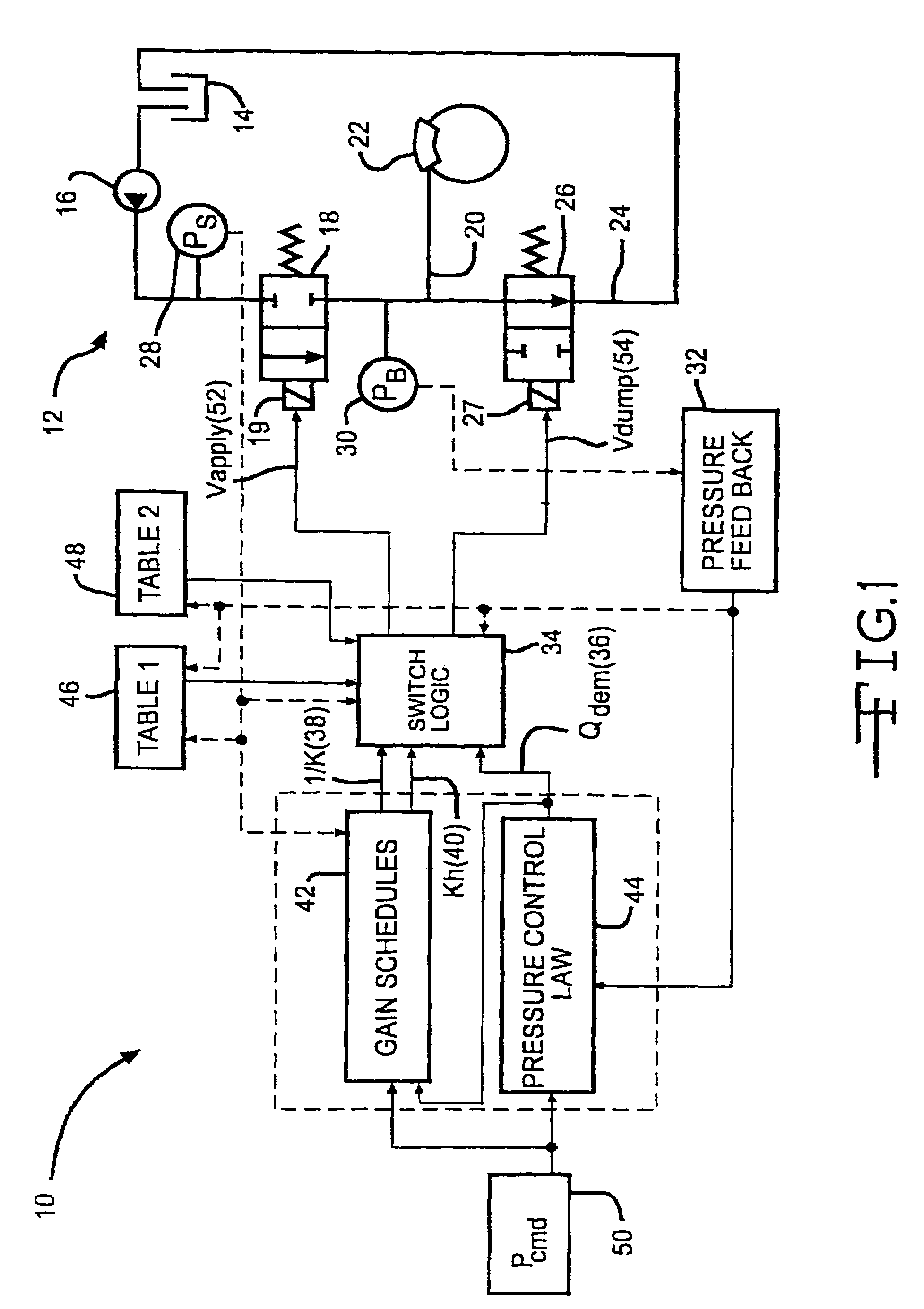
[0022]Referring now to the drawings, there is illustrated in FIG. 1 a portion 10 of the electronic circuitry processing braking signals that implements a pressure control algorithm according to the present invention, together with a greatly simplified schematic representation of a typical EHB system 12. A more detailed description of an EHB system for which the algorithm of the present invention may suitably be used is described in U.S. Pat. No. 5,941,608 to Campau et al., the disclosure of which is hereby incorporated by reference. However, it should be understood that it is believed that the present invention may suitably be practiced in a variety of other EHB systems, including without limitation, the EHB system described in the SAE Technical Paper Series No. 950762, “Intelligent Braking for Current and Future Vehicles”, and No. 960991, “Electrohydraulic Brake System—The First Approach to Brake-By-Wire Technology”, the disclosures of which are also incorporated by reference. It shou


PUM


Abstract

An electrohydraulic brake system where brake pressure is controlled by the combined action of an apply valve and a dump valve by the implementation of a method of controlling the voltage applied to the apply and dump valve. The EHB pressure control system receives a desired wheel pressure command and, with a caliper pressure feedback signal, implements an algorithm to compute one voltage command for the apply valve and another for the dump valve, corresponding to a requested flow from the hydraulics. The voltage command drives current control electronics. The electronics in turn power the solenoids of the proportional apply and dump poppet valves to control flow in or out of the brakes and modulate wheel pressure as required. Use of the algorithm to control the electromagnetic poppet valves achieves the commanded pressure at a vehicle's brakes reliably and with good control in all states of flow through the valve. The algorithm is a function of the existing pressure within the system and whether there is bulk or leakage flow through the valves.

Description


Claims


Application Information

Patent Timeline
Owner KELSEY HAYES CO
Why Eureka
Try Eureka