Connector for interfacing intravascular sensors to a physiology monitor

a technology of physiology monitor and connector, which is applied in the direction of coupling device connection, angiography, catheter, etc., can solve the problems of high insertion force, awkward manipulation of rotary connector type, and limited room for error

Inactive Publication Date: 2007-09-25
VOLCANO CORP
View PDF48 Cites 73 Cited by
  • Summary
  • Abstract
  • Description
  • Claims
  • Application Information

AI Technical Summary

Benefits of technology

The present invention relates to connects two parts together that are designed specifically for monitoring their physical condition or how they react differently during exercise activities such as running, walking, swimming, etc., without causing damage due to excessive pressure on them. This helps maintain good health over time while improving overall performance.

Problems solved by technology

In this patented technical problem addressed in that patents relates to improving the accuracy and reliability of detecting diseases like arterial occultation due to vibrational stress on blood vessels caused by heartbeats. Current methods involve invasively inserting special tools with ultrasonic probes inside the patient's veins during medical examination, but these techniques require expensive instrumentation and trained staff members. There currently exist non-contact pressure monitors attached externally onto patients without requiring them themselves. However, current solutions may be complicated and difficult to use because they rely heavily on operator skill level and experience.

Method used


Image

  • Connector for interfacing intravascular sensors to a physiology monitor
  • Connector for interfacing intravascular sensors to a physiology monitor
  • Connector for interfacing intravascular sensors to a physiology monitor

Examples


Embodiment Construction

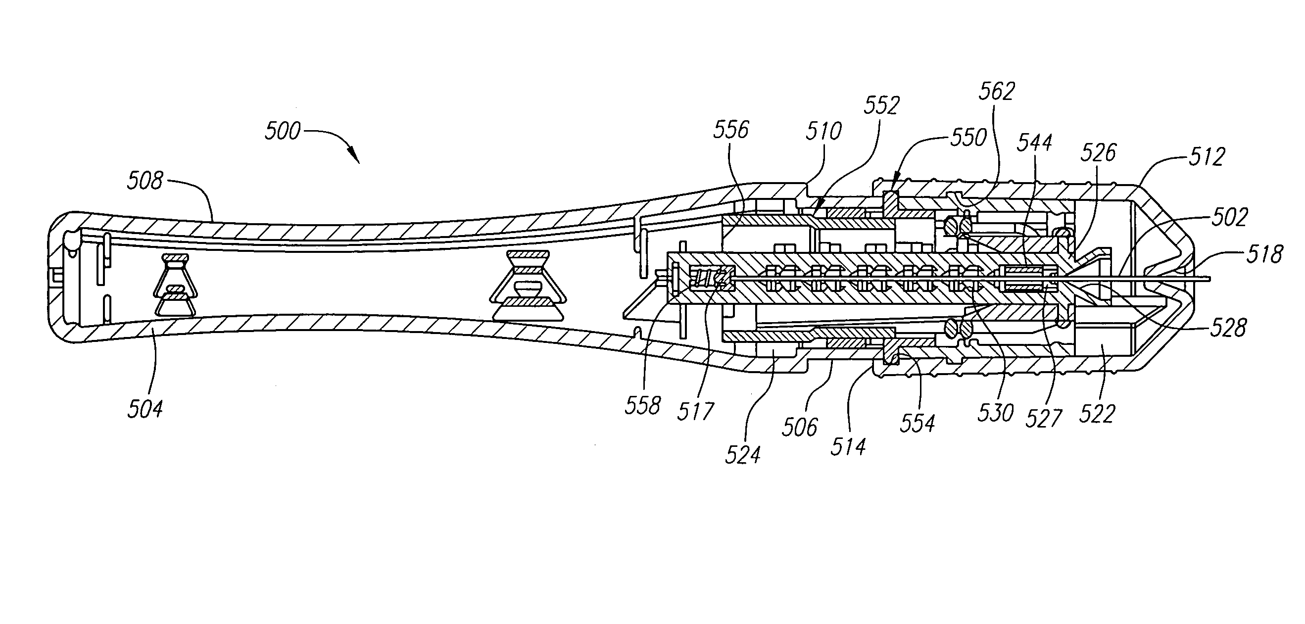
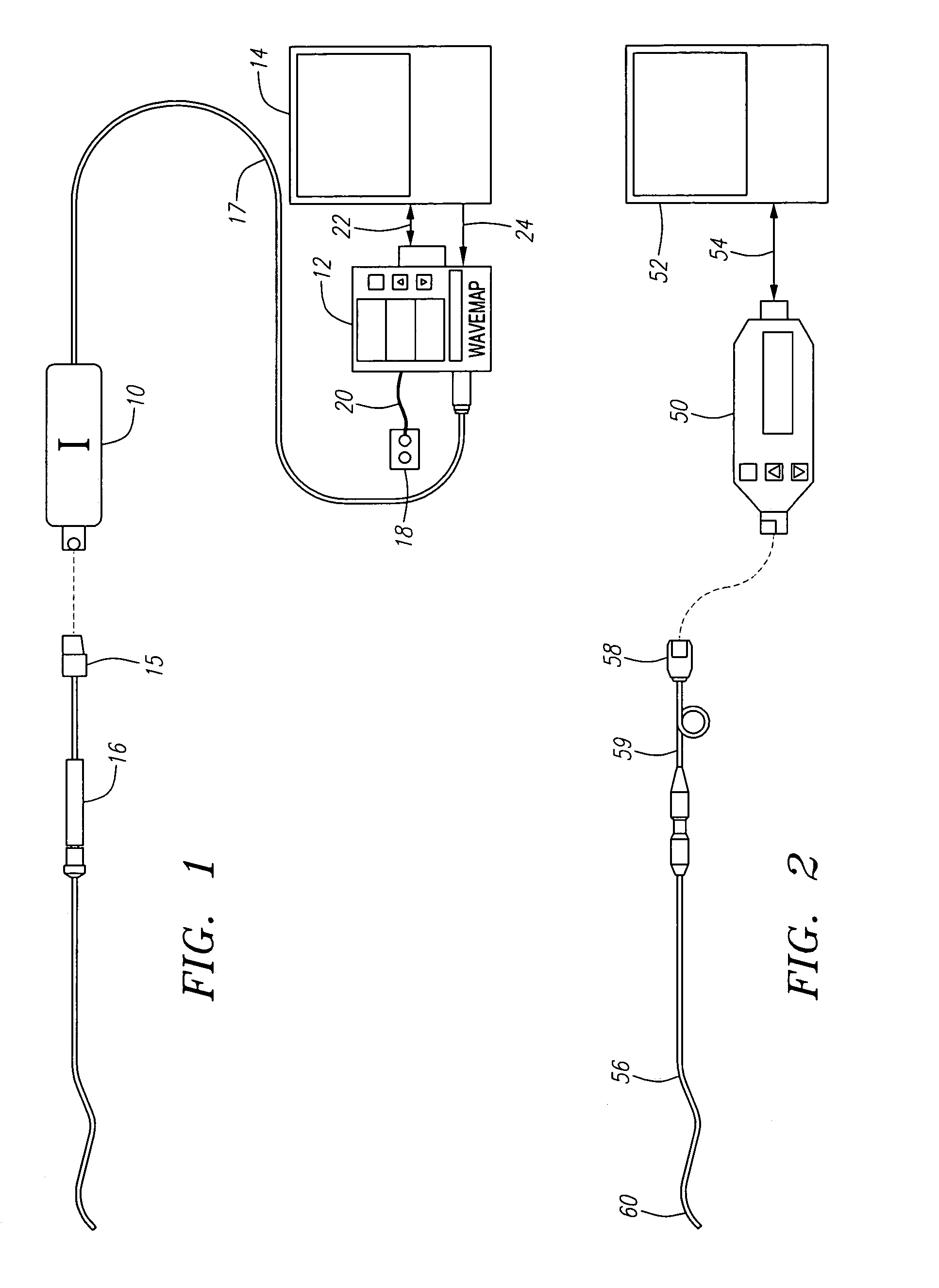
[0038]In general, an exemplary signal conditioning device embodying the present invention, described herein below with respect to FIG. 2, is designed to interface a guide wire-mounted pressure sensor to a standard physiology (e.g., blood pressure) monitor. The signal conditioning device processes a signal received from the guide wire-mounted pressure sensor and presents a normalized signal to any of multiple different physiology monitors having potentially differing signal requirements.

[0039]From the point of view of overall system setup, the exemplary signal conditioning device reduces the number of power sources, as well as the distinct cables and physically distinct apparatuses, required to conduct intravascular blood pressure measurements. These desirable attributes are achieved by having the conditioning device receive and / or utilize a differential sensor excitation signal, transmitted by known physiology monitors in a novel manner.

[0040]Known signal conditioning devices utilize


PUM


Abstract

A connector for connecting a flexible elongate member having a sensor mounted thereon to a physiology monitor includes a housing, an electrical contact member disposed within the housing, the electrical contact member having a plurality of axially spaced contact members, a cable having a plurality of conductors being electrically connected to respective axially spaced contact members, and a sleeve having an opening therein which communicates with an internal passage of the housing. The sleeve is moveable between an open position and a closed position. An interlock mechanism may also be provided to prevent the sleeve from moving from the open position to the closed position.

Description


Claims


Application Information

Patent Timeline
Owner VOLCANO CORP
Why Eureka
Try Eureka