Light source for an image-generating unit

Inactive Publication Date: 2008-12-16
CONTINENTAL AUTOMOTIVE GMBH
View PDF25 Cites 4 Cited by
  • Summary
  • Abstract
  • Description
  • Claims
  • Application Information

AI Technical Summary

Benefits of technology

[0024]Secondary optics are advantageously arranged downstream from the primary optics, which are associated with the light module itself, in the beam path which originates from the light source. These secondary optics may expediently comprise a reflector, with the reflector preferably being designed to be totally reflective, at least in places, thus virtually eliminating optical losses. One particularly cost-effective solution is for the reflector to be composed of a transmissive polymer. In this case, the reflector has an external contour which is essentially in the form of a cone or pyramid, with the cross section of the reflector widening in the main light propagation direction, for beam formation. In detail, it is expedient for the light which emerges from the primary optics of the light module to enter an input side of the reflector, to be virtually exclusively totally reflected in the reflector, and to emerge in a light beam from an output side. In this case, the reflector is particularly advantageously designed for use in an image-production unit according to the invention if it emits a widening light beam which has a boundary surface which forms an angle of about 5°-15° with a central axis which runs centrally through the light beam in the main light propagation direction. This feature can be implemented better if the external contour of the reflector is convex, in which case it has been found to be particularly expedient for the external contour of the reflector to be in the form of a rotational paraboloid which widens in the main light propagation direction, and for the rotational paraboloid to be based on a fifth-order polynomial. The input losses of the reflector can be reduced to a minimum by the provision of a recess, which at least partially holds a light means provided on the light module, on the input side.
[0025]If additional focusing of the input light is desired, it is worthwhile for the recess to have an end surface which is arranged opposite the light source in the direction of the central axis and has convex curvature in the direction of the light source.
[0026]Particularly if it is desirable for the light source of the image-production unit to emit over an area, it is worthwhile arranging a plurality of reflectors, which are associated with light modules, adjacent to one another. In order to avoid excessive irregularities of the illumination in the area of the junctions between the individual reflectors, it is expedient for the reflectors to have an output surface which allows arrangement alongside one another virtually without any gaps, for example by the output surface being rectangular. In order to avoid inhomogeneities of the brightness distribution over the overall area of the output surfaces of the reflectors occurring despite this, it is expedient for a common light-mixing module to be arranged downstream from the reflectors in the beam path. Depending on the physical space requirements, a translucent display of the image-production unit can be arranged directly downstream from the light-mixing module in the beam path, or with the interposition of a reflector or mirror which folds the beam path. A reflector or mirror such as this also makes it possible to increase the depth impression or the distance impression of the virtual image to the driver in the case of a head-up display. Depending on the focusing effect of the secondary optics, the output area of the secondary optics may be approximately the same size as the display area through which the light can pass. The light-mixing module, which is preferably adjacent to the secondary optics, may expediently be in the form of a box with a light inlet side and a light outlet side, and side walls which reflect inward. The length of extent in the direction of the beam path must be defined as a function of the magnitude of the brightness differences in the area of the output surface of the secondary optics. Any inhomogeneities in the brightness and other visual disturbance effects which originate from the light source or from the secondary optics can be overcome additionally, or in the case of minor differences exclusively as well, by means of a scattering disk which is arranged in the beam path between the light module and the display.

Problems solved by technology

The stringent requirements, in particular relating to a high level of external light from the environment, on the brightness of the light source to be used for a head-up display, with only a small amount of available physical space at the same time, place major demands on the development process, all the time.
The brightness, which is produced by light means, is either so low that a large number of light means, for example normal semiconductor light-emitting diodes, are required, or the individual light means have such a high power loss, which must be dissipated as heat, that the complexity and space requirement for cooling no longer comply with the specified financial and technical constraints.

Method used


Image

  • Light source for an image-generating unit
  • Light source for an image-generating unit
  • Light source for an image-generating unit

Examples


Example

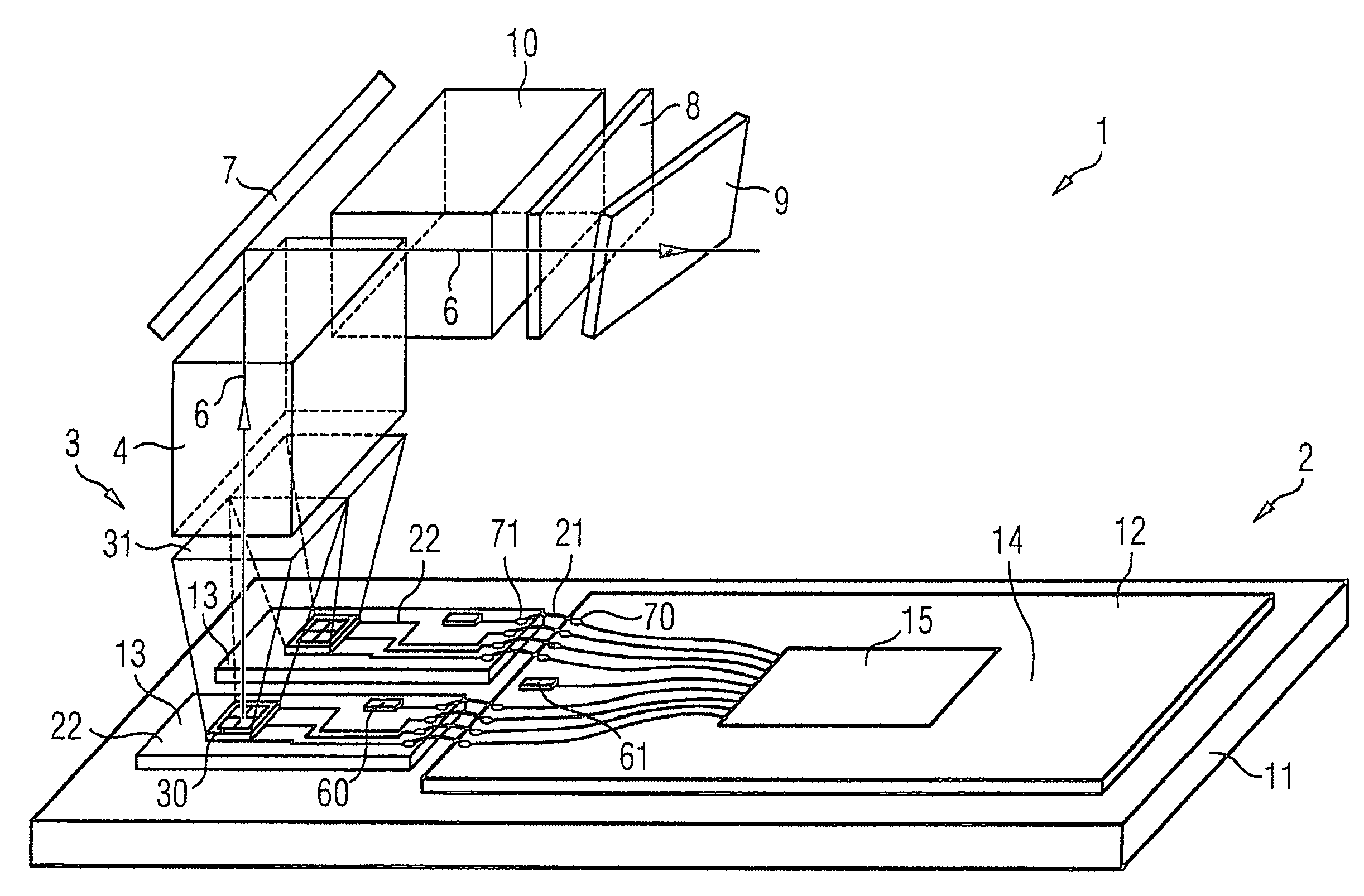
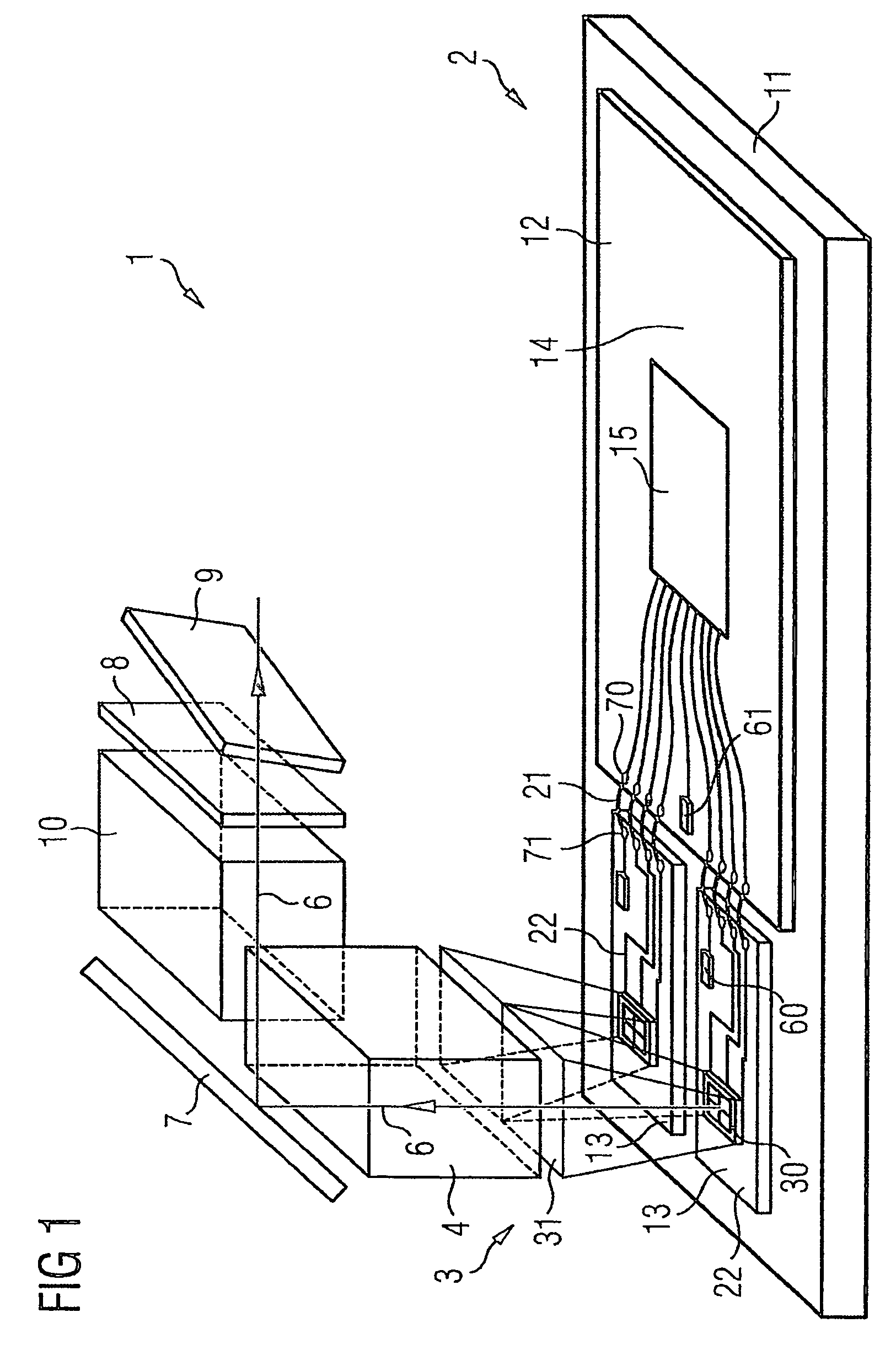
[0031]FIG. 1 shows an image-production unit 1 according to the invention with the major components following the beam path 5 originating from the light source 2, in a main light propagation direction 6: the light source 2, the secondary optics 3, the light-mixing module 4, the mirror 7, the scattering disk 8 and the display 9, in which case a light box 10 can also optionally be arranged between the mirror 7 and the scattering disk 8, in the manner illustrated here.

[0032]The light source 2 essentially comprises a mount 11, a drive module 12 and light modules 13. The mount 11 is in the form of a heat sink composed of aluminum, on which the drive module 12 and the light modules 13 are adhesively bonded, by an unpopulated flat face. In this case, the adhesive bonding in each case satisfies stringent demands for thermal conductivity and temperature resistance. The drive module 12 has a second mount element 14, which is in the form of a printed circuit board and is fitted with drive electron


PUM


Abstract

The invention relates to a light source (2) comprising at least one light module (13) and one control module (12) provided with a control electronics system. The invention also relates to an image-generating unit (1) for a head-up display provided with an inventive light source (2). Traditional solutions require too much construction space or cannot be mass-produced in order to obtain sufficient brightness. The aim of the invention is to combine a high degree of brightness, little construction space and mass-producibility, particularly for a head-up-display. According to the invention, the light module (13) and the control module (12) respectively comprise their own carrier element (14, 22)and are firmly connected to a common carrier (11). The light module (13) is connected to the control module (12) by means of first electrical lines which are configured in such a way that thermally induced relative movements between the control modules (12) and light module (13) are received in a trouble-free manner by modification of the form of the lines.

Description


Claims


Application Information

Patent Timeline
Owner CONTINENTAL AUTOMOTIVE GMBH
Why Eureka
Try Eureka