Optical block assembly

a technology of optical blocks and assemblies, applied in the field of optical block assemblies, can solve the problems of increased rotational speeds, limited image sensor size, and rotational inertia of longer optical blocks, and achieve the effects of reducing cctv camera applications, reducing angular inertia, and compactness

Inactive Publication Date: 2009-09-01
GE SECURITY INC
View PDF40 Cites 5 Cited by
  • Summary
  • Abstract
  • Description
  • Claims
  • Application Information

AI Technical Summary

Benefits of technology

The present inventors describe how small cameras can now use miniature photonics technology called Optropic Lenses®(OLS), allowing them to capture high quality images without being too bulky at all times. This makes it possible to creature digital cameras that work better on different types of sensory equipment like still video cameras.

Problems solved by technology

Technological Problem: Current Optical Block Assembly used in Video Surveying Devices like CCT Veters suffer from issues related to limited space available for mounting large imagers while still providing high performance capabilities. Expansion of these devices requires increasing their dimensions but there can only be enough room left around them to allow for smaller versions. Additionally, current designs require long opticals because they cannot handle higher levels of illumination compared to lower level signals.

Method used


Image

  • Optical block assembly
  • Optical block assembly
  • Optical block assembly

Examples


Embodiment Construction

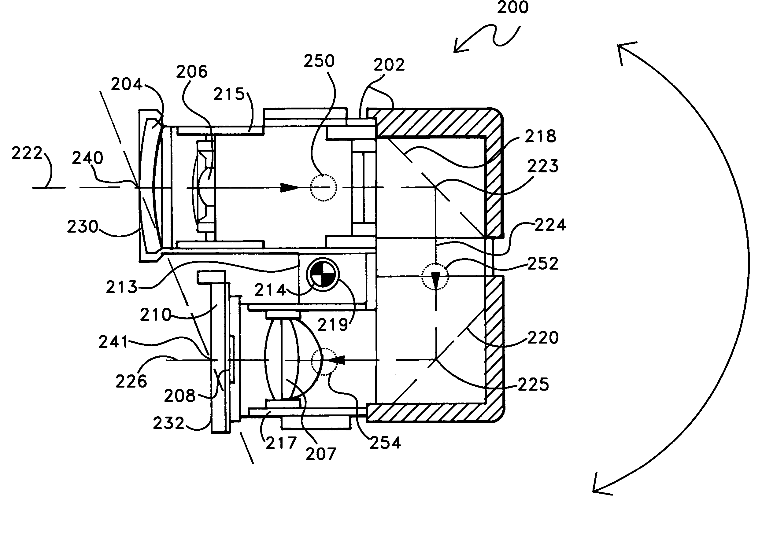
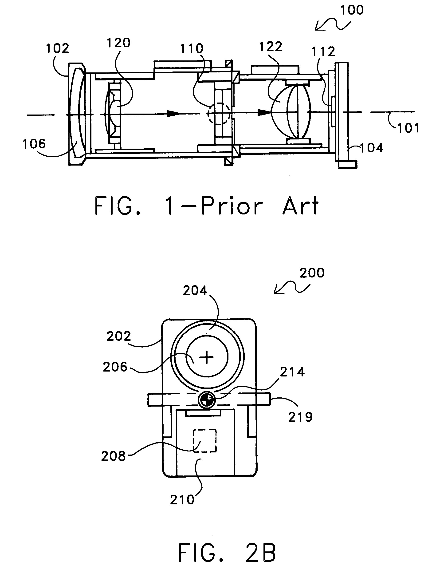
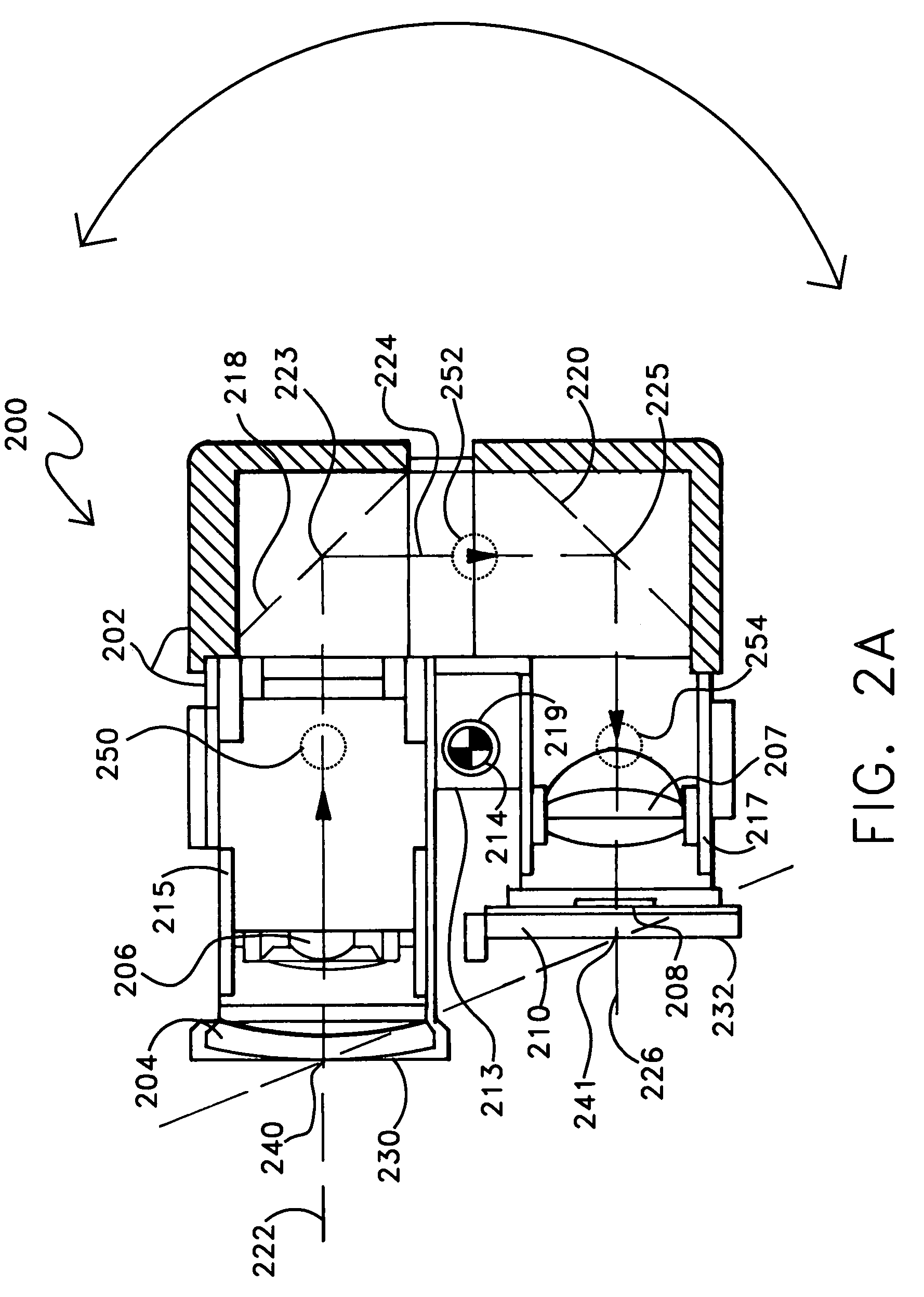
[0031]FIGS. 2A, 2B and 3A illustrate respective side, frontal and perspective views of one exemplary embodiment of a multiple stage folded light path optical block assembly according to the disclosed systems and methods. In this regard, FIGS. 2A, 2B and 3 illustrate a dual-stage folded light path optical block assembly 200 that includes an optical block housing 202 that maintains in operative relationship a pair of 90-degree reflecting prisms 218 and 220, a movable zoom lens assembly 206, a movable focus lens assembly 207 and image sensor circuit board assembly 210. As illustrated, prisms 218 and 220 are operatively disposed to form an optical path between a light or image gathering lens 204 and an image sensor 208 of assembly 200.

[0032]Still referring to FIGS. 2A, 2B and 3A, light gathering lens 204 is configured to provide a first or initial linear light path defined between light gathering lens 204 at front end 230 of assembly 200 and first 90-degree reflecting prism 218. As shown,


PUM


Abstract

Optical block assemblies having single or multi-stage folded light path lens assemblies that may be implemented to allow an optical block assembly to occupy significantly less space and/or present reduced rotational inertia to an electrical articulating mechanism. An optical assembly may be so configured for closed circuit television applications or in any other suitable video imaging application including, but not limited to, applications involving non-articulated or articulated cameras such as normal filming (e.g., motion picture film cameras or studio television cameras), camcorders, military targeting or imaging devices, etc.

Description


Claims


Application Information

Patent Timeline
Owner GE SECURITY INC
Why Eureka
Try Eureka