Electronic circuit for driving electroluminescent display

Active Publication Date: 2011-09-27
MFLEX UK
View PDF17 Cites 1 Cited by
  • Summary
  • Abstract
  • Description
  • Claims
  • Application Information

AI Technical Summary

Benefits of technology

The patent describes a method for controlling the power supplied by a system. It suggests using a special type of transistors called field effect transistors (FETs) instead of traditional resistive elements like diodes. These transistors are used to control the flow of electric current through them. By adjusting their conductivity, they can help prevent damage caused by accidental short circuits between different parts of the system's electrical components.

Problems solved by technology

The technical problem addressed in this patent is how to create a lightweight and efficient electroluminescent display without requiring expensive materials like rare metals.

Method used


Image

  • Electronic circuit for driving electroluminescent display
  • Electronic circuit for driving electroluminescent display
  • Electronic circuit for driving electroluminescent display

Examples


Embodiment Construction

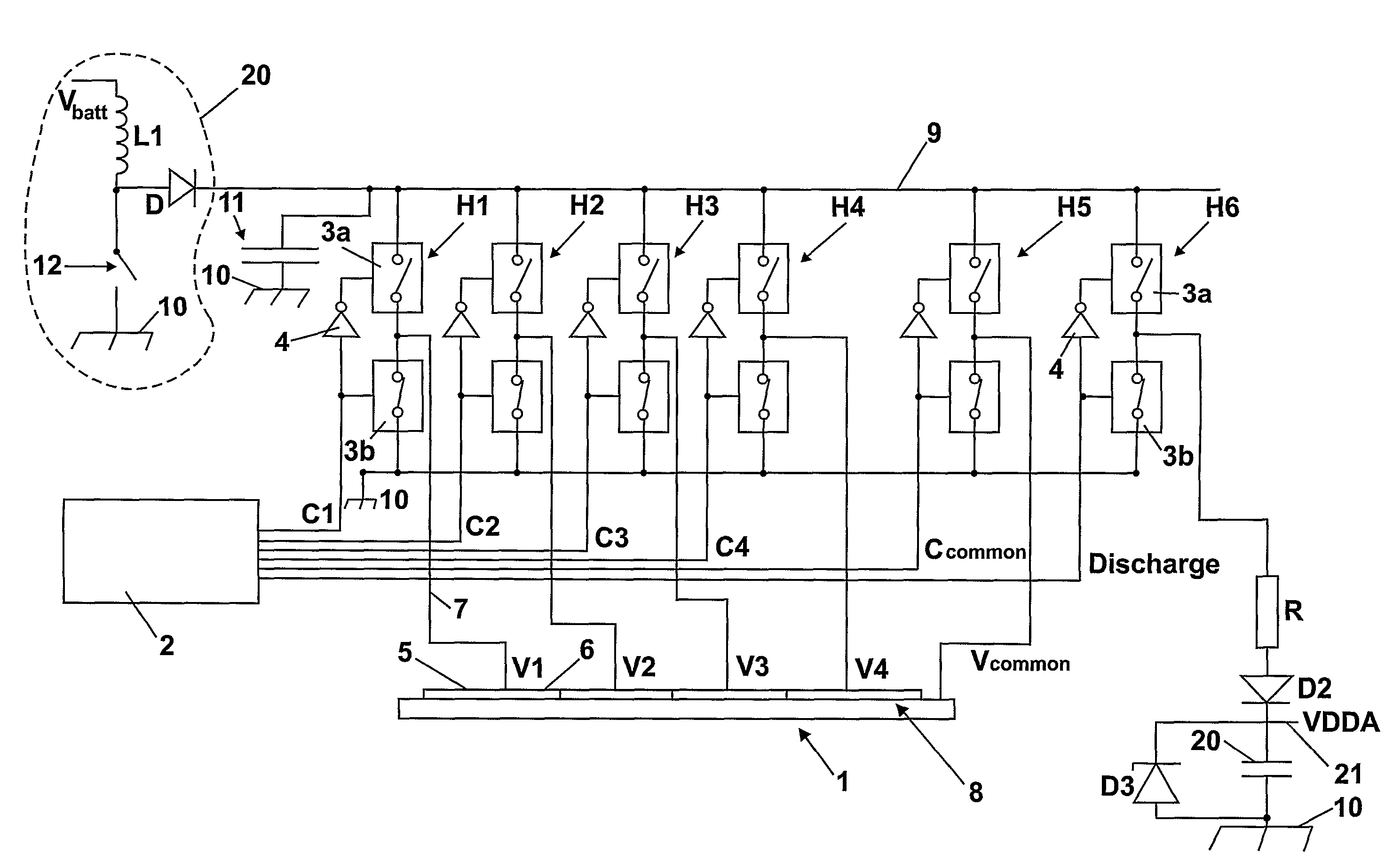
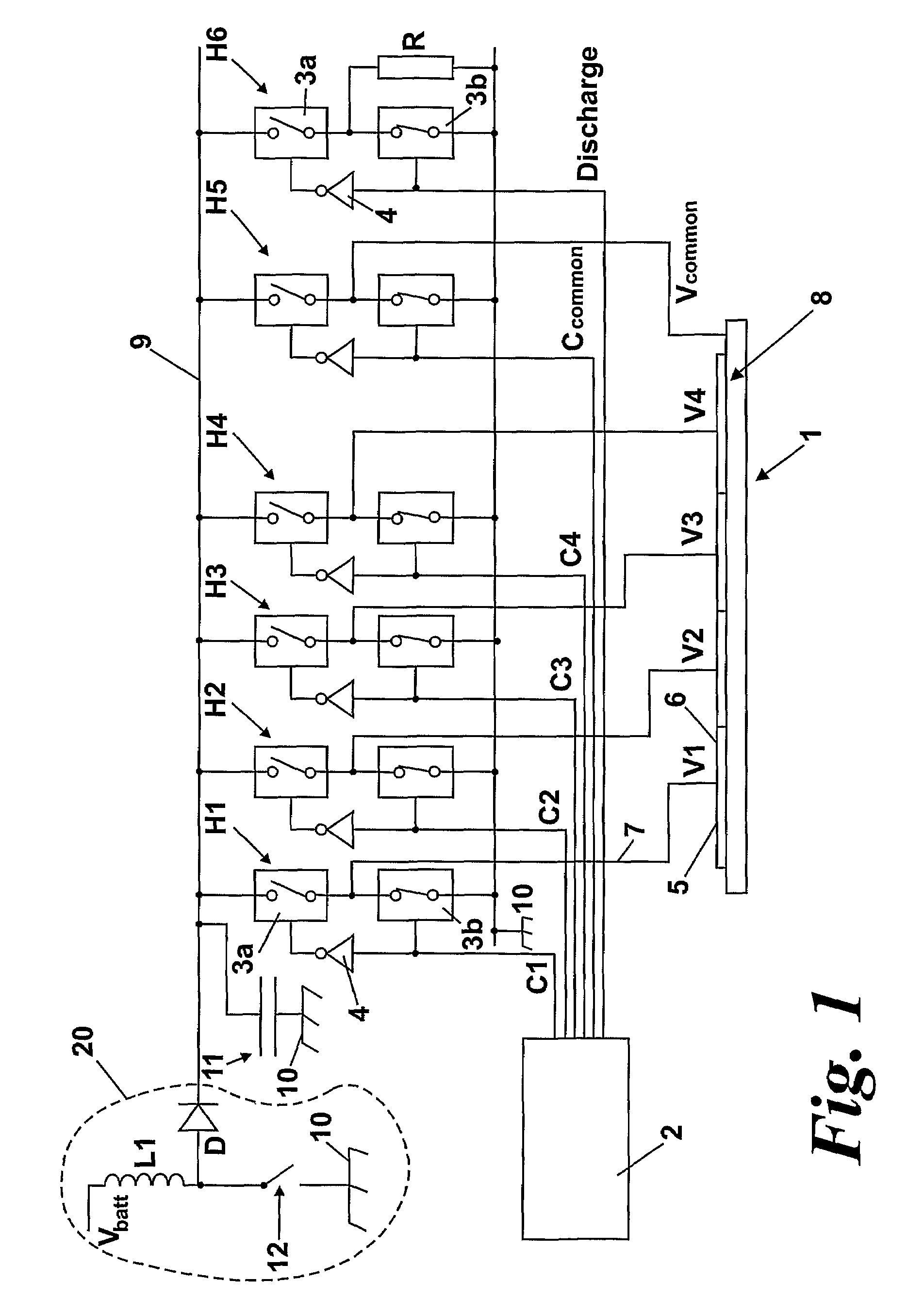
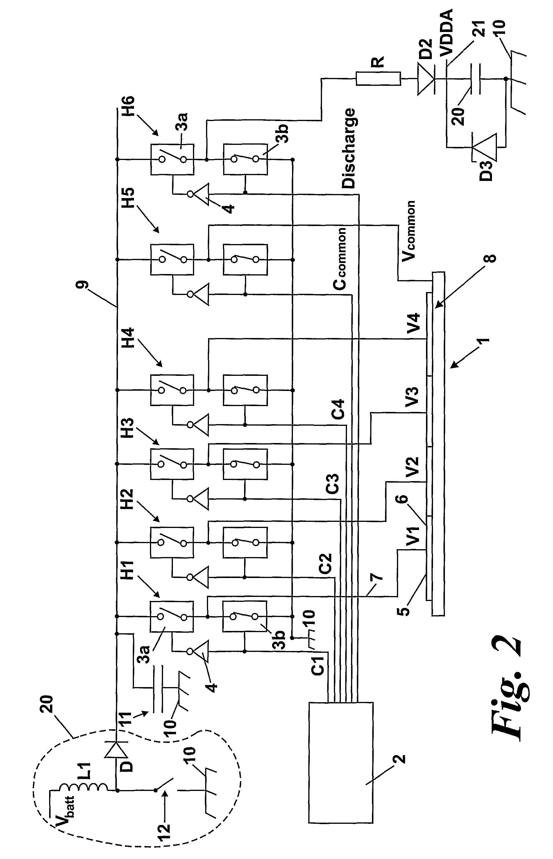
[0037]FIG. 1 shows an electronic circuit for driving an electroluminescent (EL) display 1, according to a first embodiment of the invention. For simplicity's sake, the circuit is shown as having the combination of outputs required for driving a four-segment display 1 although any number of segments is in principle possible.

[0038]The EL display 1 comprises a common electrode 8, formed of an Indium Tin Oxide (ITO) transparent common electrode, and four segment electrodes 5. The segments 6 of the display are defined by the shape of the segment electrodes 5. Application of an alternating voltage across each segment 6 by causing an alternating voltage to be present between a segment electrode and the common electrode causes that segment 6 of the EL display 1—that is the phosphor between the segment electrode 6 and the common electrode 8—to illuminate.

[0039]A flyback voltage converter 20 is provided in order to convert the voltage obtained from a battery Vbatt to a suitable voltage to power


PUM


Abstract

An electroluminescent circuit for driving an electroluminescent display having a plurality of segment electrodes and a common electrode. The circuit comprises a DC power supply, an output terminal for each of the segments and common electrodes and at least one supply half H-bridge for connecting at least one of each of the segment electrodes and the common electrode selectively to one of the DC supply and a reference voltage. Each supply half H-bridge comprises a top switch and a bottom switch in series having a junction between them. The top switch is connected to the DC supply and the bottom switch is connected to a reference voltage. A discharge circuit is provided for selectively discharging the electroluminescent display, the discharge circuit comprising a discharge half H-bridge in which a top switch is connected to the DC supply and to a discharge path.

Description


Claims


Application Information

Patent Timeline
Owner MFLEX UK
Why Eureka
Try Eureka