Subfloor drainage panel

a drainage panel and subfloor technology, applied in ventilation systems, lighting and heating apparatus, heating types, etc., can solve the problems of subfloor drainage panel moisture present, etc., and achieve the effects of low manufacturing cost, low price of sale, and easy and efficient manufacturing and marketing

Active Publication Date: 2015-02-17
MILLS HILTON R
View PDF29 Cites 45 Cited by
  • Summary
  • Abstract
  • Description
  • Claims
  • Application Information

AI Technical Summary

Benefits of technology

The technical effect of this patented technology relates to improving upon existing floor drains by providing better performance without adding extra material or requiring more expensive equipment than what was previously possible for them. This can make it easier to sell at lower costs compared to older options like plasterboard panels.

Problems solved by technology

There has been previous attempts at creating a better way to remove excess water during construction without damaging any structures such as walls or foundations. However, current solutions involve adding extra materials like sandbags or vinyl barriers to absorb liquids falling onto them while still allowing some moistenness to pass through. Additionally, existing methods require multiple steps involving fixing each layer separately, leading to increased complexity and cost issues.

Method used


Image

  • Subfloor drainage panel
  • Subfloor drainage panel
  • Subfloor drainage panel

Examples


Embodiment Construction

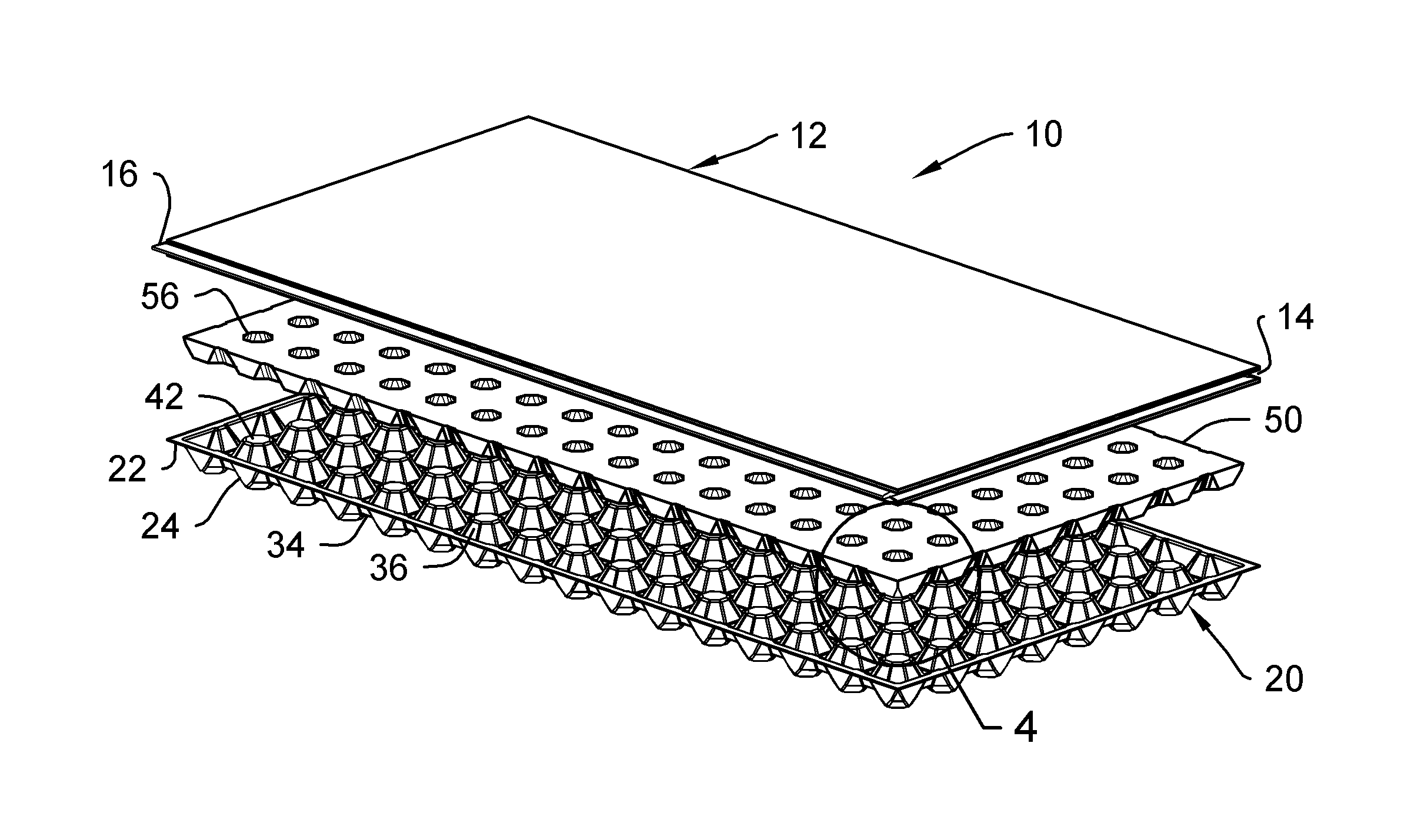
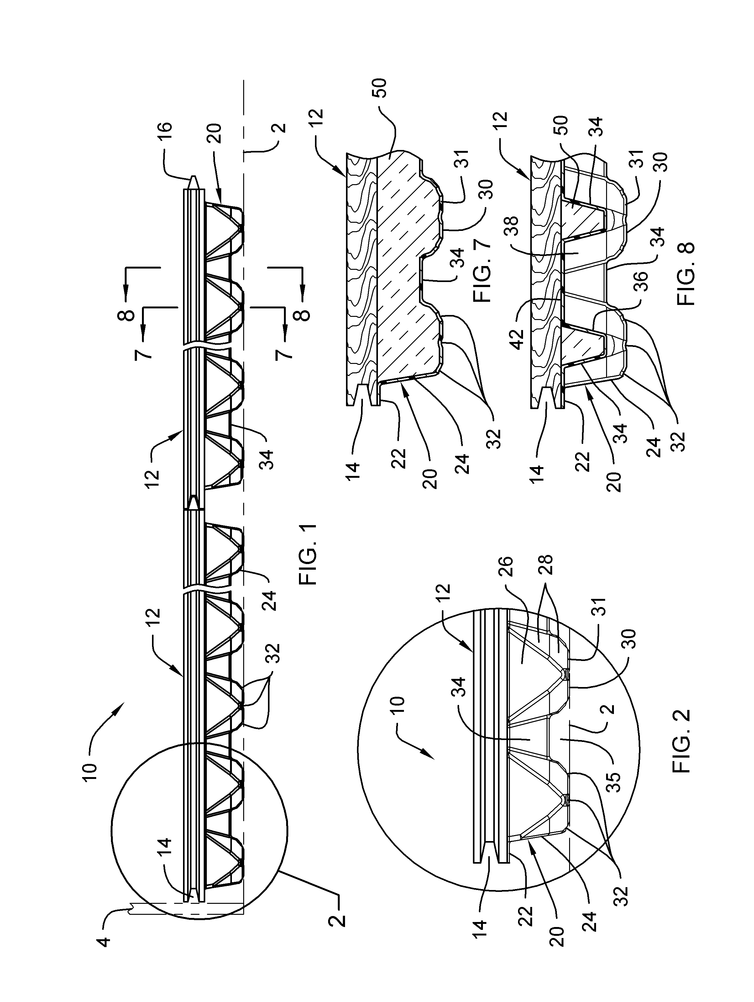
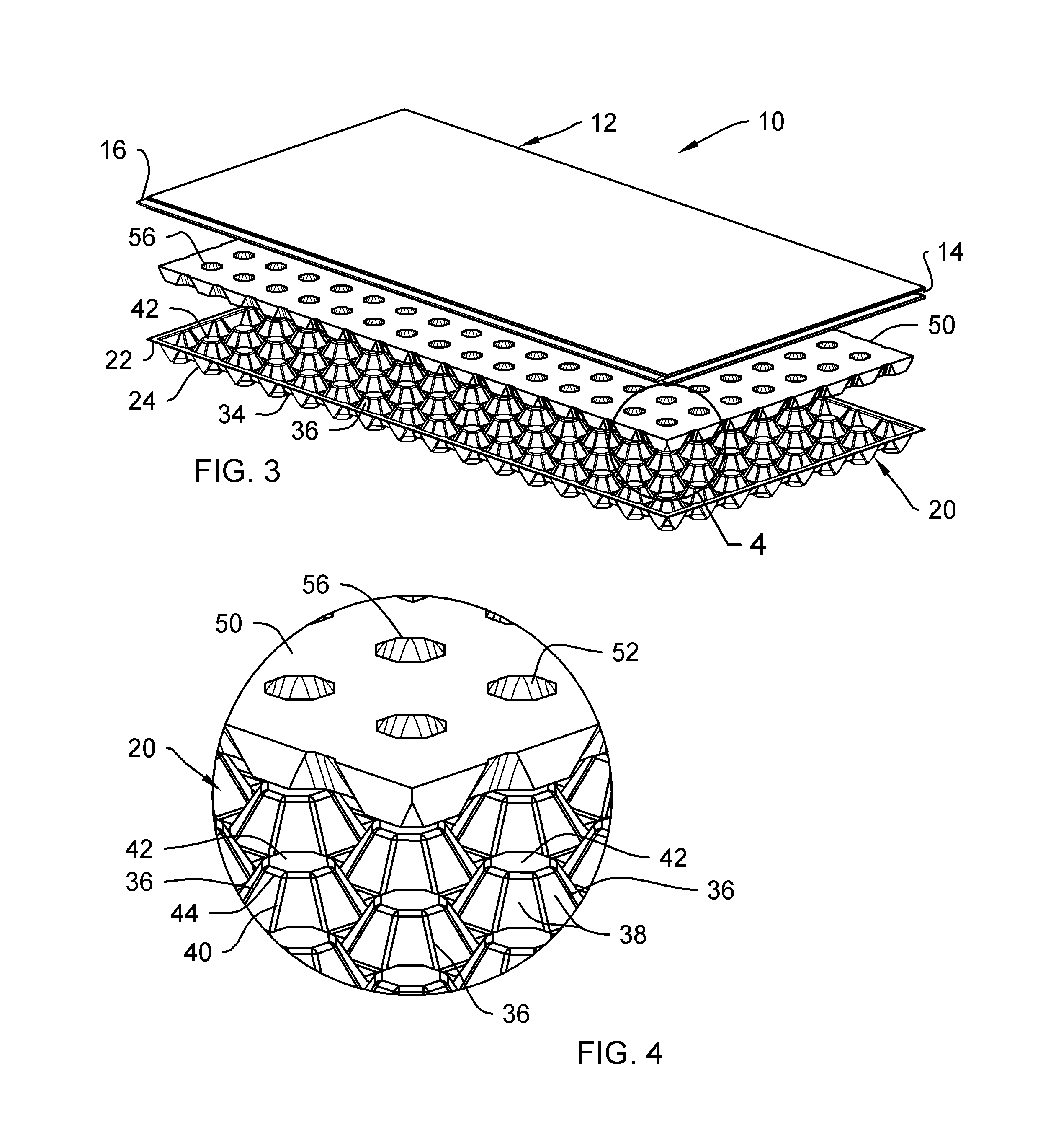
[0036]Referring now to the drawings, and particularly to FIGS. 1-11, an embodiment of the subfloor drainage panel of the present invention is shown and generally designated by the reference numeral 10.

[0037]In FIGS. 1 and 2, a new and improved subfloor drainage panel 10 of the present invention for draining moisture from a floor using a multi-component subfloor is illustrated and will be described. More particularly, the subfloor drainage panel 10 has an upper member 12 and a lower member 20. The lower member 20 is attached to the upper member 12. The subfloor drainage panel 10 rests on a surface 2, and its edges can abut against a wall or stud 4, or additional subfloor drainage panels 10. The surface 2 may be, but not limited to, a pre-existing floor, foundation or substructure. The subfloor drainage panel 10 may be used on any floor a building or vehicle, in a basement, in the bilge of a marine vessel, in an aircraft, or in any area where potential flooding or moisture damage can occ


PUM


Abstract

A subfloor drainage panel is provided for draining moisture from a floor. The subfloor drainage panel has an upper member, a lower member attached to the upper member, and an intermediate member located in the lower member. The lower member includes a plurality of first projections extending away from the upper member, a plurality of second projections extending toward the upper member, and at least one drain hole defined in the first projections. The first projections support the subfloor drainage panel on a surface. The intermediate member has a plurality of openings each configured to receive therethrough a portion of one of the second projections so as to contact and support the lower member. The lower member is configured to define a gap between a portion of the lower member and the surface, with the gap being configured to allow fluid to pass therethrough.

Description


Claims


Application Information

Patent Timeline
Owner MILLS HILTON R
Why Eureka
Try Eureka