Method for interlocking switching current mirror and stabilizing output current

A technology of switching current and current mirror, which is applied in the field of current mirror to achieve the effect of increasing the uniformity of output current and reducing the amount of current difference

Inactive Publication Date: 2007-10-24
SILICON TOUCH TECH INC
View PDF0 Cites 1 Cited by
  • Summary
  • Abstract
  • Description
  • Claims
  • Application Information

AI Technical Summary

Problems solved by technology

Through the above method of alternately switching the current mirror, although the current output by the output nodes OUT1 and OUT2 is I+(a+b)/2, the curre

Method used


Image

  • Method for interlocking switching current mirror and stabilizing output current
  • Method for interlocking switching current mirror and stabilizing output current
  • Method for interlocking switching current mirror and stabilizing output current

Examples


Embodiment Construction

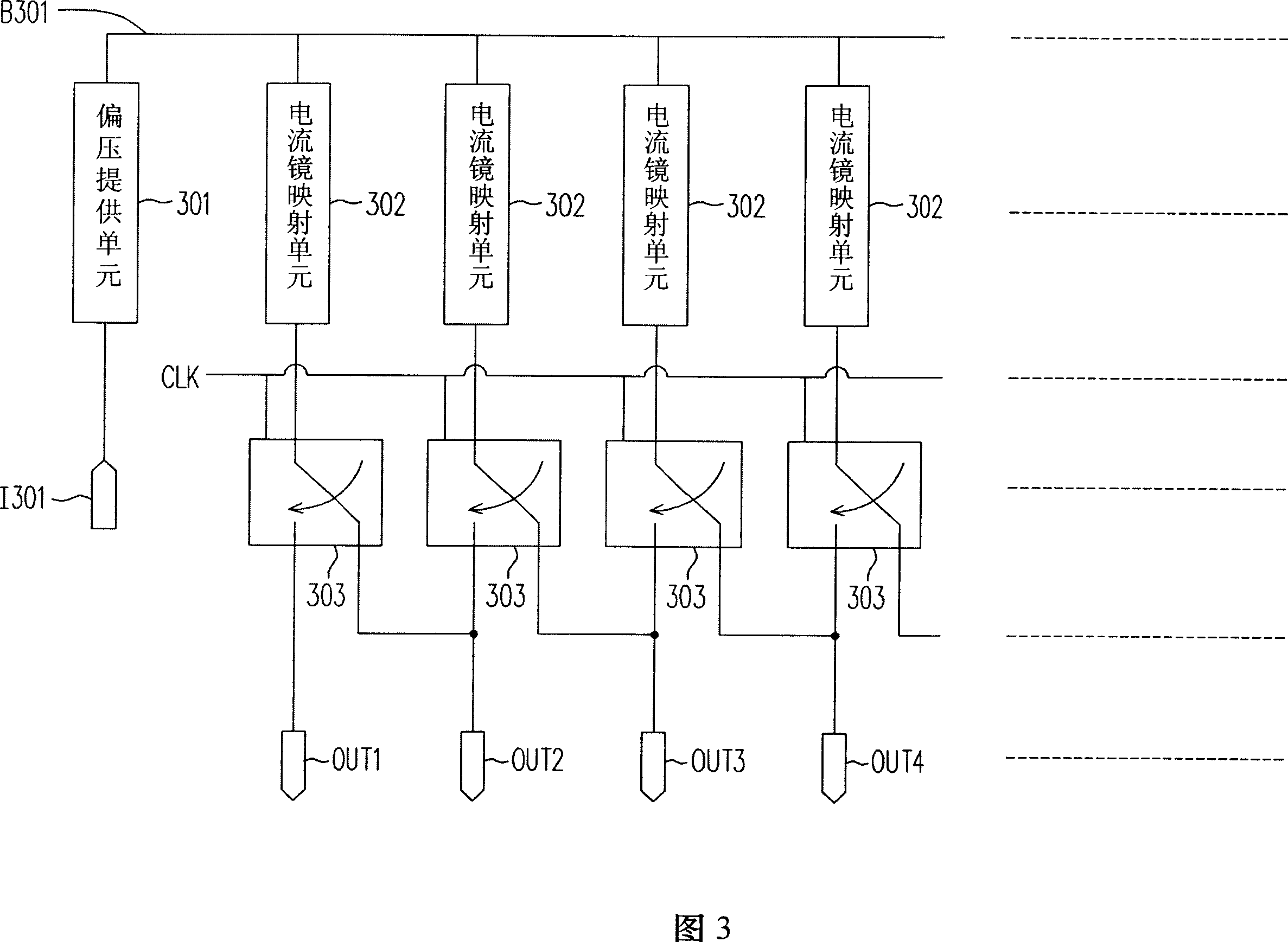
[0053] FIG. 3 is a circuit block diagram of a chain switching current mirror according to an embodiment of the present invention. Referring to FIG. 3 , the current mirror includes a bias voltage supply unit 301 , a plurality of current mirror mapping units 302 , a plurality of switching elements 303 and a plurality of output nodes OUT1˜OUTN.

[0054] The bias supply unit 301 provides a reference bias voltage B301 at the reference voltage terminal R301 according to the current received by the input terminal I301. Each current mirror mapping unit 302 includes a bias receiving end and an output end, and its bias receiving end is coupled to the reference voltage end R301 to receive the reference voltage B301. According to the reference voltage B301, the output terminal of the current mirror mapping unit 302 outputs an output current. Each switch element 303 includes a first terminal, a second terminal, a third terminal and a control terminal, and the control terminal receives the cl


PUM


Abstract

The invention relates to a method for linked switch a current mirror and stabilizing output current, wherein the current mirror comprises a plurality of output nodes, a bias provider, a plurality of current mirror projectors and a plurality of switch elements. The bias provider provides a reference bias voltage according to received current, each current mirror projector is coupled with the bias provider to receive the reference voltage to output an output current according to the reference voltage, the control end of each switch element receives a clock signal via which to couple the first end with the second end or the third end, the first end of the i-th switch element is coupled with the output of the i-th current mirror projector while the second end is coupled with the i-th output node, and the third end is coupled with the i+1-th output node, i natural number.

Description


Claims


Application Information

Patent Timeline
Owner SILICON TOUCH TECH INC
Why Eureka
Try Eureka