Shell-and-tube type heat exchanger employing crossed spiral tube

A technology of shell-and-tube heat exchangers and spiral tubes, which can be used in exhaust gas recirculation heat exchangers, exhaust attachments, and engine inlets. It can solve the problems of low heat exchange efficiency and achieve improved heat exchange effects and good exhaust gas. Use the effect of the effect

Active Publication Date: 2008-01-09
BEIJING U BRIDGE CHAOYANG +1
View PDF0 Cites 4 Cited by
  • Summary
  • Abstract
  • Description
  • Claims
  • Application Information

AI Technical Summary

Benefits of technology

This technology uses an improved design for a device called Cross Spiral Groovelike Heat Exchange Tubule (CSHT). When there's some flow from one part towards another, they move along with them around on their own axis. These movements cause fluids inside these devices to become more like waves or bouncing back against each other create interference patterns which help increase thermal efficiency between different parts of the system. By allowing certain gases within this structure to pass over while still being able to absorb energy efficiently, we aimed to achieve higher levels of cooling performance compared to traditional methods such as water mist spray systems.

Problems solved by technology

Technologies aim to develop better designs for heat exchanges within vehicles' air conditionings systems without compromizing safety measures while maintaining good thermal management properties. One approach involves improving the efficiency of conventional heat exchange devices like evaporators and condensors. Another solution focuses on enhancing the effectiveness of the traditional method involving adding fins onto certain parts of the vehicle's interior components. These improvements help decrease pollution levels during operation.

Method used


Image

  • Shell-and-tube type heat exchanger employing crossed spiral tube
  • Shell-and-tube type heat exchanger employing crossed spiral tube
  • Shell-and-tube type heat exchanger employing crossed spiral tube

Examples


Embodiment 1

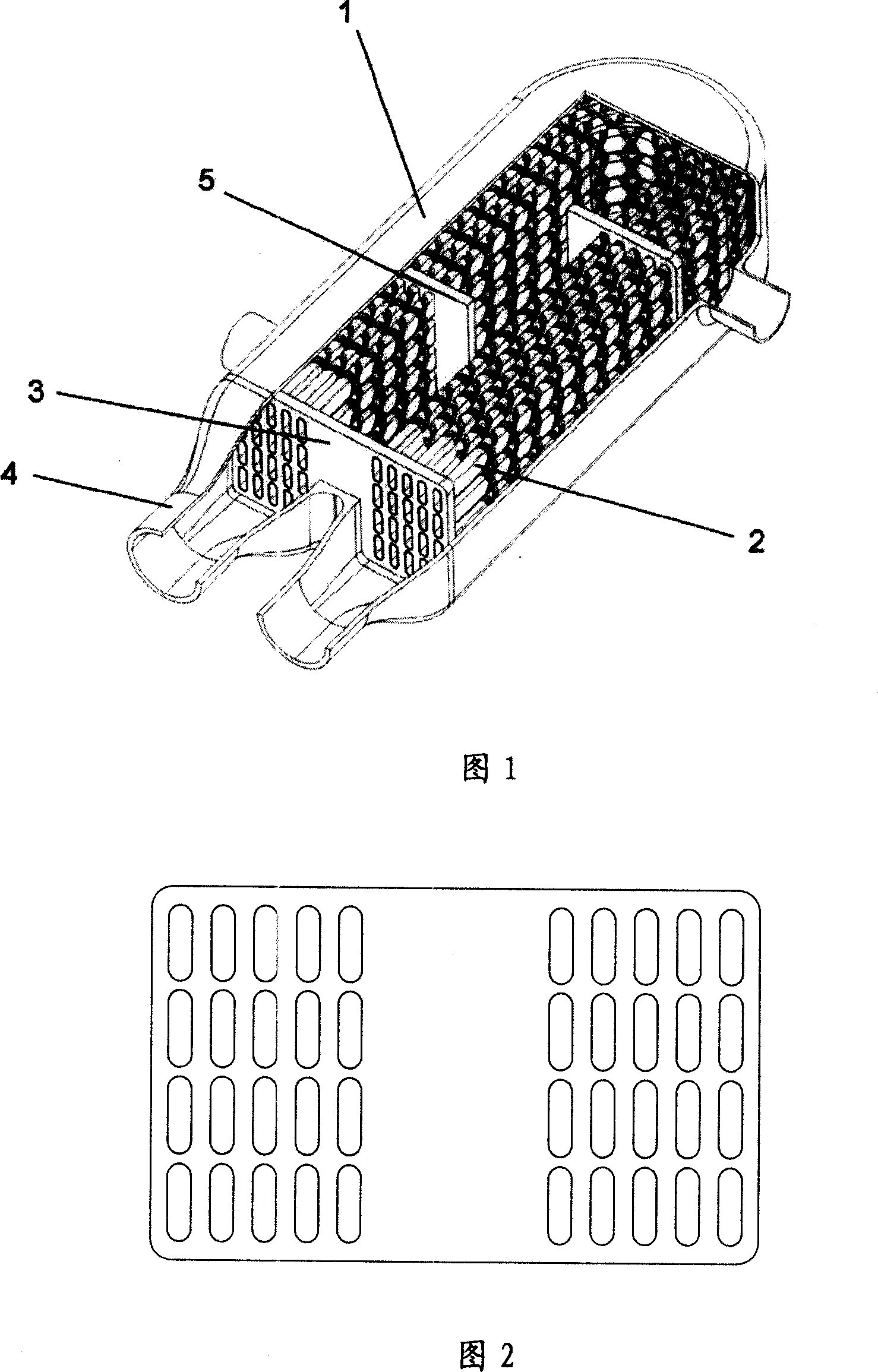
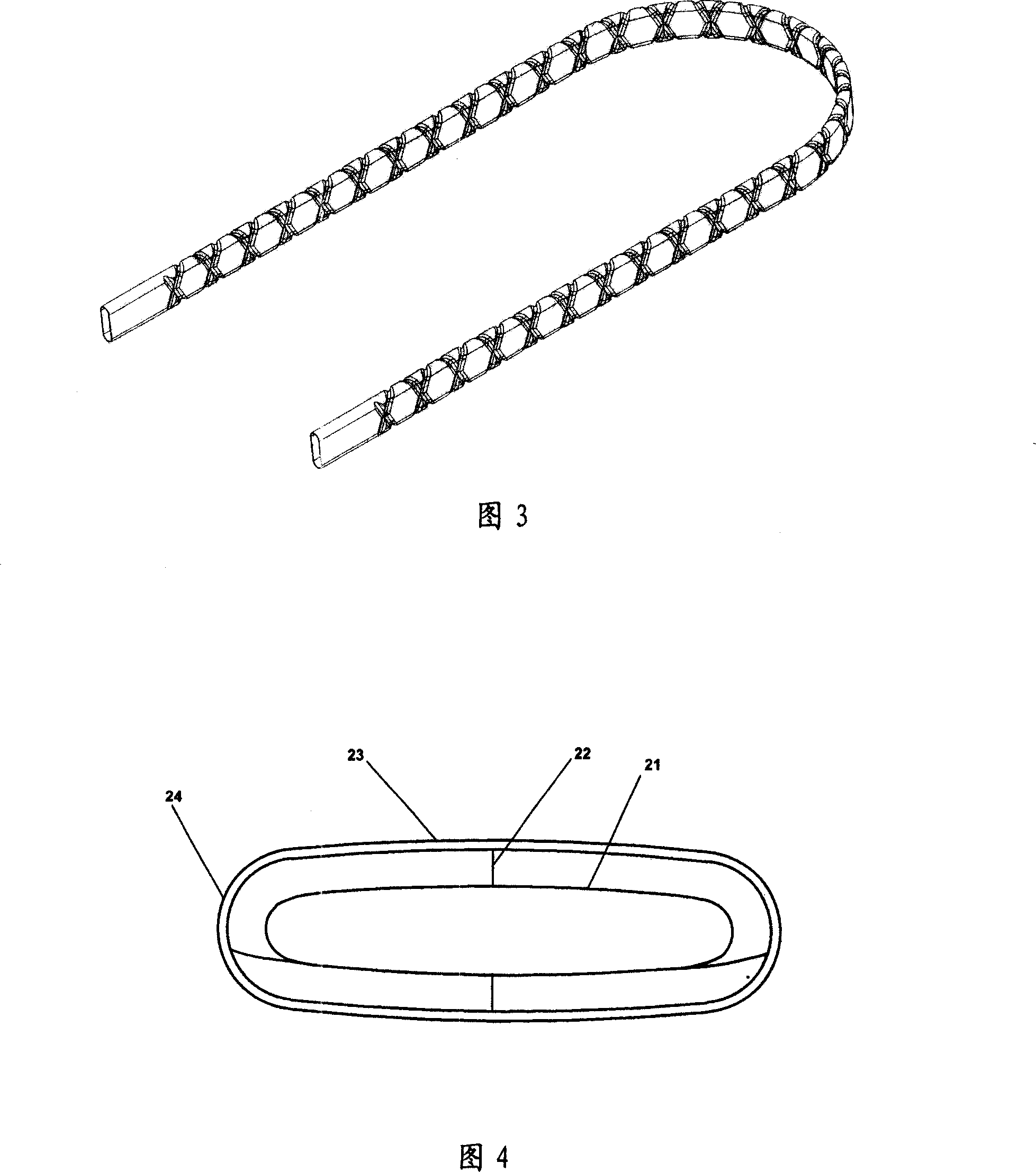
[0022] 1 and 2 are respectively a three-dimensional structural schematic diagram and a cross-sectional schematic diagram at the tube sheet of the first embodiment of the present invention. The serial numbers in the figure represent: 1. Shell, 2. Heat exchange tube, 3. Tube sheet, 4. Exhaust gas inlet and outlet, 5. Baffle plate. Figure 1 is a schematic diagram of an arrangement of flat cross-helical tubes in a U-shaped tube heat exchanger. One end of the shell 1 is provided with an opening, and a tube plate 3 is provided at the opening, and the two ends of the U-shaped heat exchange tube 2 (ie, the exhaust gas inlet end and the exhaust gas outlet end 4) are assembled on the same side of the tube plate; There is a through hole for fixing the U-shaped heat exchange tube on the end surface of the joint of the exhaust gas inlet and outlet 4; the heat exchange tube 2 is composed of two straight pipe sections and one bent pipe section, and is in a U-shape. The two ends of the U-shaped

Embodiment 2

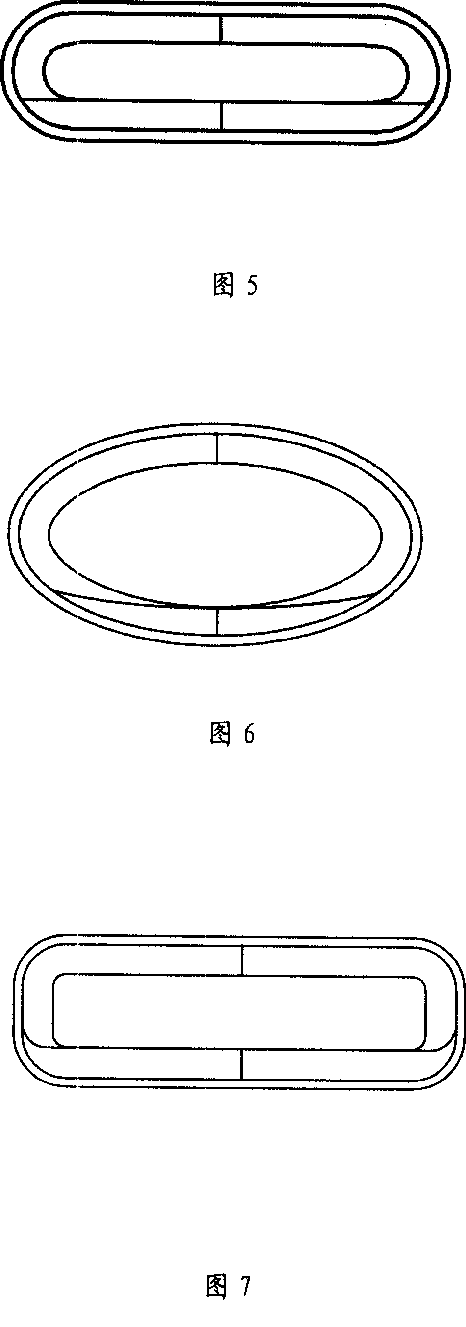
[0031] Fig. 5 is a sectional view of the heat exchange tube in this embodiment. The difference between this embodiment and the embodiment described in FIG. 4 above is that the cross-sectional shape of the stainless steel pipe body is flat, the two opposite long sides are straight lines, and the relatively short sides are arc-shaped convex semicircular arc surfaces from the inside to the outside. Such a setting can improve heat exchange efficiency.

[0032] The flat spiral heat exchange tube arranged in the exhaust gas recirculation cooler not only increases the heat exchange area compared with the circular tube, but also strengthens the disturbance of the fluid in the tube. Because the flat tube is not symmetrical to the center of the round tube, the distance between the geometric center of the flat spiral tube and the tube wall is smaller than the distance between the circular spiral tube and the tube wall, and most of the fluid in the tube can participate in heat exchange , an

Embodiment 3

[0034] Fig. 6 is a sectional view of the heat exchange tube in this embodiment. This embodiment is a modification based on the embodiment described in Figure 4 above, and the entire cross-section of the heat exchange tubes is connected smoothly, that is, for the convenience of processing, when the cross-sectional shape of the spiral groove is removed, the The cross-sectional shape of the pipe body is set to an ellipse;


PUM

PropertyMeasurementUnit
Helix angleaaaaaaaaaa
Depthaaaaaaaaaa

Abstract

The invention relates to a tube-shell type heat exchanger which used the U-shaped cross-helical tube, involving an engine exhaust recycle heat exchanger. For improving the engine exhaust recycle system, accelerating the exhaust cooling and increasing the heat exchange efficiency. The heat exchanger includes the heat exchange tube, shell and the tube board, the heat exchange tube is the U shaped siphon, whose two ends fixed on the same tube board, the heat exchange tube is the stainless steel tube which has the entad raised cross-helical groove on the surface, the cross is the 'X'-shaped, the section shape of the stainless steel pipe is a special flat shape, and the height and width of the section shape in the flat shape heat exchange tube are unlikeness. Because of the application of the cross-helical heat exchange tube, the tube inside and outside produce the turbulent flow, not easy to dirty and increase the heat exchange efficiency. The heat exchanger has a compact structure, is particularly suitable for the exhaust gas recycle coolers of a vehicle engine, reduce the discharge of the nitrogen oxygen compound and enhance the exhaust discharge performance indicators, at the same time, the invention can also be used as the mid cooler of a turbocharger system to improve the engine performance.

Description


Claims


Application Information

Patent Timeline
Owner BEIJING U BRIDGE CHAOYANG
Why Eureka
Try Eureka