Playing method of video/audio file and playing system using this method
A technology of audio-visual files and playing methods, applied in parts of TV systems, analog security/charging systems, electrical components, etc., can solve the problems that users do not bring obvious convenience
- Summary
- Abstract
- Description
- Claims
- Application Information
AI Technical Summary
Problems solved by technology
Method used
Image

Examples
Embodiment 1
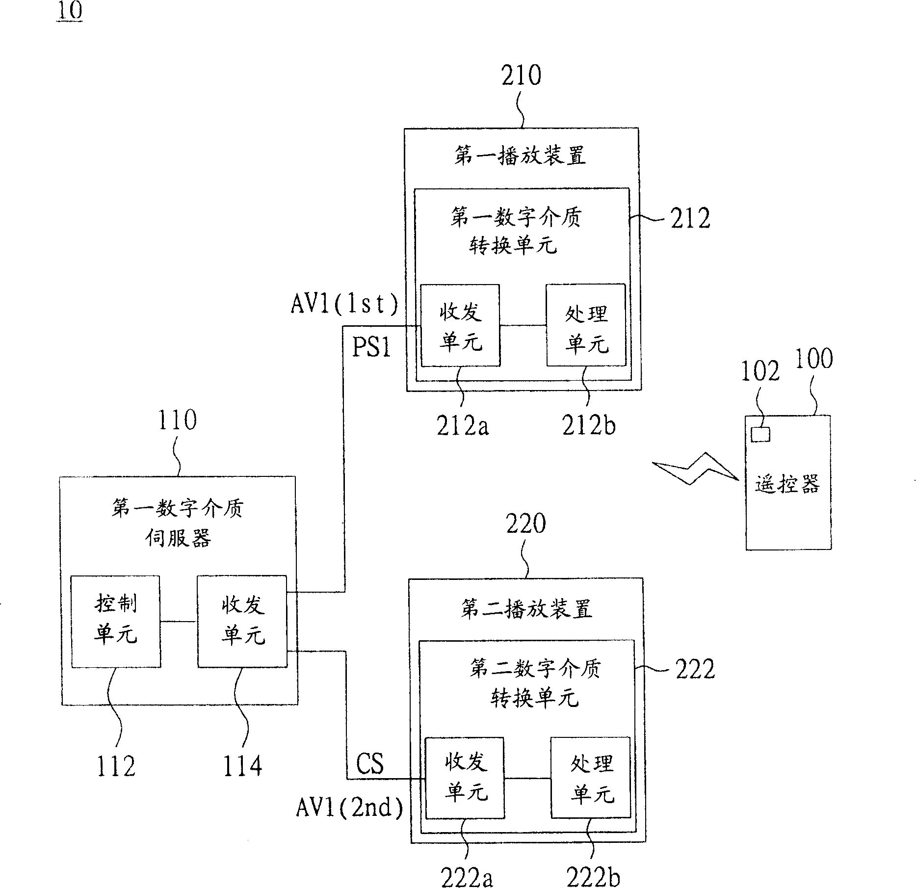
[0033] Please refer to figure 1 , which shows a functional block diagram of the digital media playback system according to Embodiment 1 of the present invention. The digital media playback system 10 includes a first digital media server 110 , and a first playback device 210 and a second playback device 220 coupled to the first digital media server 110 . The first playback device 210 and the second playback device 220 can be a TV or a projector respectively. The first playback device 210 and the second playback device 220 have a first digital media adapter (DMA) 212 and a second digital media adapter 222 respectively. The first digital media conversion unit 212 and the second digital media conversion unit 222 can be external devices, respectively coupled with the first playback device 210 and the second playback device 220, and can also be directly built in the first playback device 210 and the second playback device 210. inside the playback device 220.
[0034] Wherein, the fi
Embodiment 2
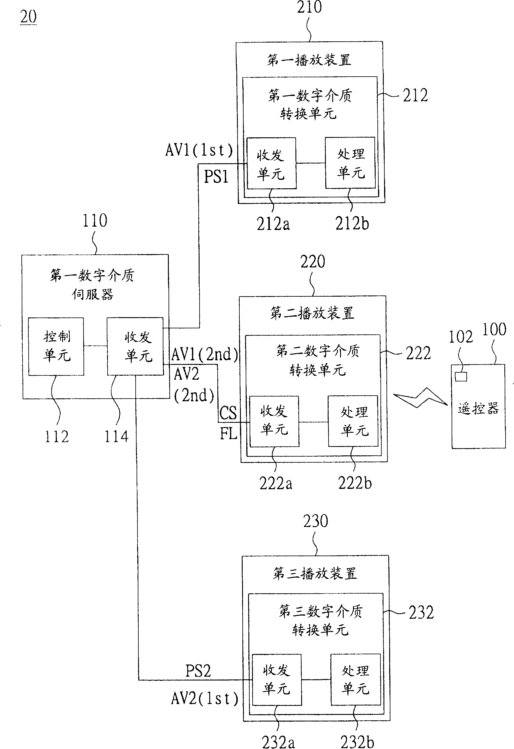
[0044] Please refer to image 3 , which shows a functional block diagram of the digital media playing system according to Embodiment 2 of the present invention. The main difference between the digital media playback system 20 and the digital media playback system 10 of the first embodiment is that the first digital media server 110 can also be coupled with a third playback device 230 . Therefore, this embodiment means that the digital media server can be coupled with and controlled by more playback devices, so that users can watch video and audio files uninterruptedly in more places. The third playback device 230 has the same functions as the first playback device 210 and the second playback device 220, so the third digital media conversion unit 232 of the third playback device 230, and the transceiver unit 232a, processing unit 232b and The first and second digital media conversion units 212, 222 and the transceiver units 212a, 222a and processing units 212b, 222b included ther
Embodiment 3
[0056] Please refer to Figure 6 , which shows a functional block diagram of a digital media playback system according to Embodiment 3 of the present invention. The main difference between the digital media playback system 30 and the digital media playback system 20 of the second embodiment is that a second digital media server 120 is added, which is coupled to the second playback device 220 and the third playback device 230 respectively. That is to say, this embodiment means that the present invention can be applied to audio-visual systems connected to more digital media servers, so that users can watch more audio-visual files without interruption. The function of the second digital media server 120 is the same as that of the first digital media server 110 , so the functions of the control unit 122 and the transceiver unit 124 are also the same as those of the control unit 112 and the transceiver unit 114 . The transceiver unit 124 is used to output the second video file AV2 to
PUM
 Abstract
Description
Claims
Application Information
 - R&D Engineer
- R&D Manager
- IP Professional
- Industry Leading Data Capabilities
- Powerful AI technology
- Patent DNA Extraction
Browse by: Latest US Patents, China's latest patents, Technical Efficacy Thesaurus, Application Domain, Technology Topic.
© 2024 PatSnap. All rights reserved.Legal|Privacy policy|Modern Slavery Act Transparency Statement|Sitemap