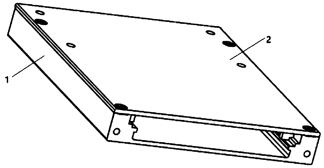
Pop-up device applied to data recording disk box

A pop-up device and data recording technology, applied in data recording, record information storage, record carrier structural parts, etc., can solve the problems of time-consuming, screw tightening torque is not easy to control, etc., achieve less use of accessories, shorten maintenance time, Convenient pop-up effect

Pending Publication Date: 2019-12-13
西安视成航空科技有限公司
View PDF0 Cites 0 Cited by
  • Summary
  • Abstract
  • Description
  • Claims
  • Application Information

AI Technical Summary

Benefits of technology

This patented design allows for easy removal or replacement of an optical storage device (such as CD) from its drive without having to remove everything that holds them up inside itself. Its technical effect includes simplifying the process while reducing the number of parts needed during installation.

Problems solved by technology

Technically speaking, there are different types of storage devices called recorders with removably attached discs: Pluggables (also known as USB drives) or hard drive cards. These devices require specialized hardware like connectors between them when they're being installed on an aircraft. However, these connections may take longer than usual because users have difficulty controlling how well their heads fit together during installation/removal procedures. Therefore, we propose create a new way to make it easier by providing a mechanism where the recording disc cannot easily get loose from its original position inside without requiring extra effort.

Method used


Image

  • Pop-up device applied to data recording disk box
  • Pop-up device applied to data recording disk box
  • Pop-up device applied to data recording disk box

Examples


Embodiment Construction

[0021] In order to more clearly understand the above objects, features and advantages of the present invention, the present invention will be described in detail below in conjunction with the accompanying drawings and specific embodiments. It should be noted that, in the case of no conflict, the embodiments of the present application and the features in the embodiments can be combined with each other.

[0022] In the description of the present invention, it should be noted that the terms "center", "upper", "lower", "left", "right", "vertical", "horizontal", "inner", "outer" etc. The indicated orientation or positional relationship is based on the orientation or positional relationship shown in the drawings, or the orientation or positional relationship that is usually placed when the product of the invention is used, and is only for the convenience of describing the present invention and simplifying the description, rather than indicating or implying References to devices or elem


PUM


Abstract

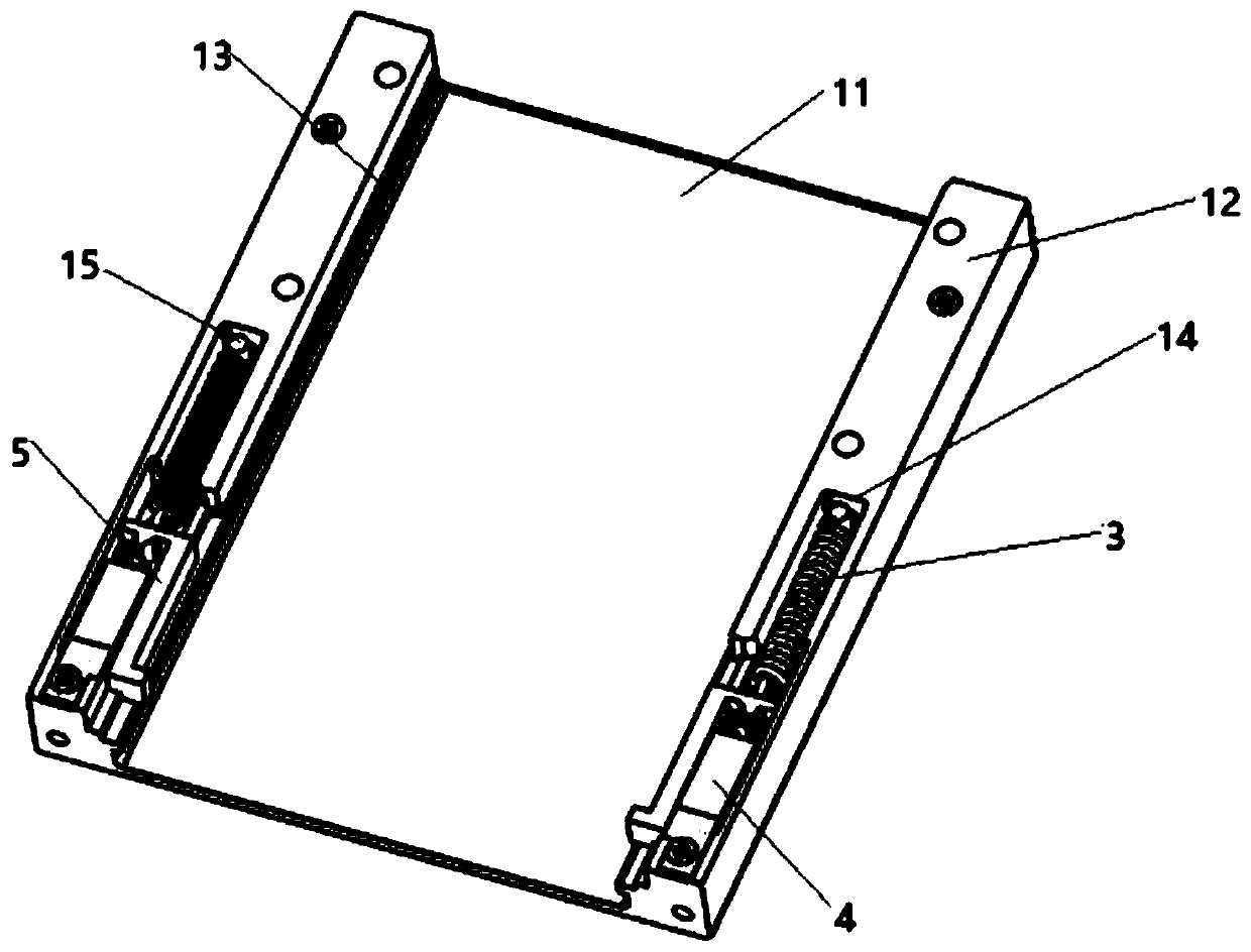
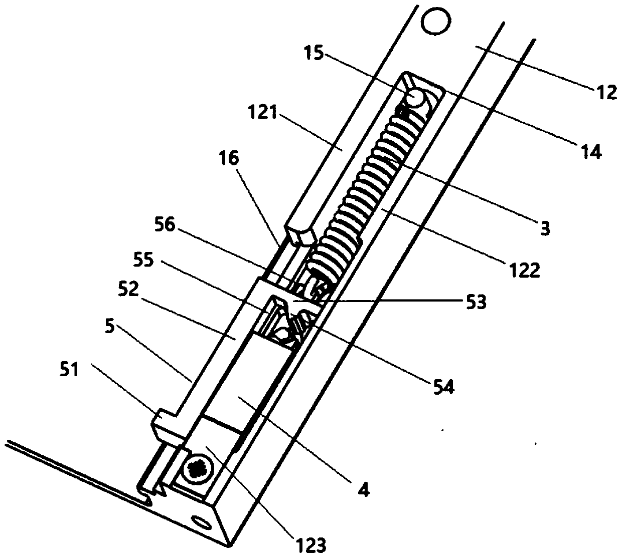
The invention provides a pop-up device applied to a data recording disk box. The pop-up device comprises a pop-up bottom shell and a cover plate covering the pop-up bottom shell. A strip-shaped grooveis formed in a side plate of the pop-up bottom shell. A spring and a sliding block are arranged in the strip-shaped groove. A cavity is formed in the sliding block. A central bulge is formed in the center in the cavity. The mold cavity consists of a first mold cavity part, a second mold cavity part and a third mold cavity part. The bottom of the second cavity part is of a boss structure higher than the bottom of the first cavity part and the bottom of the third cavity part. The first sliding block splicing part extends towards the cavity to form a vertex angle. A concave part is formed in theposition, opposite to the vertex angle, of the center protrusion, a first guide slope and a second guide slope are arranged at the bottom of the junction, close to the vertex angle, of the upper endof the second cavity part and the upper end of the third cavity part, a clamping hook is further arranged in the cavity, an inserting hole is formed in the third side plate splicing part, and the lower end of the clamping hook is inserted into the inserting hole. The recording disc is simple in overall structure, few accessories are used, and popping-up operation of the recording disc can be achieved more conveniently.

Description


Claims


Application Information

Patent Timeline
Owner 西安视成航空科技有限公司
Why Eureka
Try Eureka