Finger base joint transmission mechanism of dexterous robot hand with adjustable pre-tightening and transmission inter space
A technology of transmission mechanism and base joint, applied in the directions of manipulators, chucks, manufacturing tools, etc., can solve the problems of high processing cost, space limitation, complex structure, etc., and achieve the effect of low processing cost, simple structure, and reasonable force balance effect.
- Summary
- Abstract
- Description
- Claims
- Application Information
AI Technical Summary
Benefits of technology
Problems solved by technology
Method used
Image

Examples
specific Embodiment approach 1
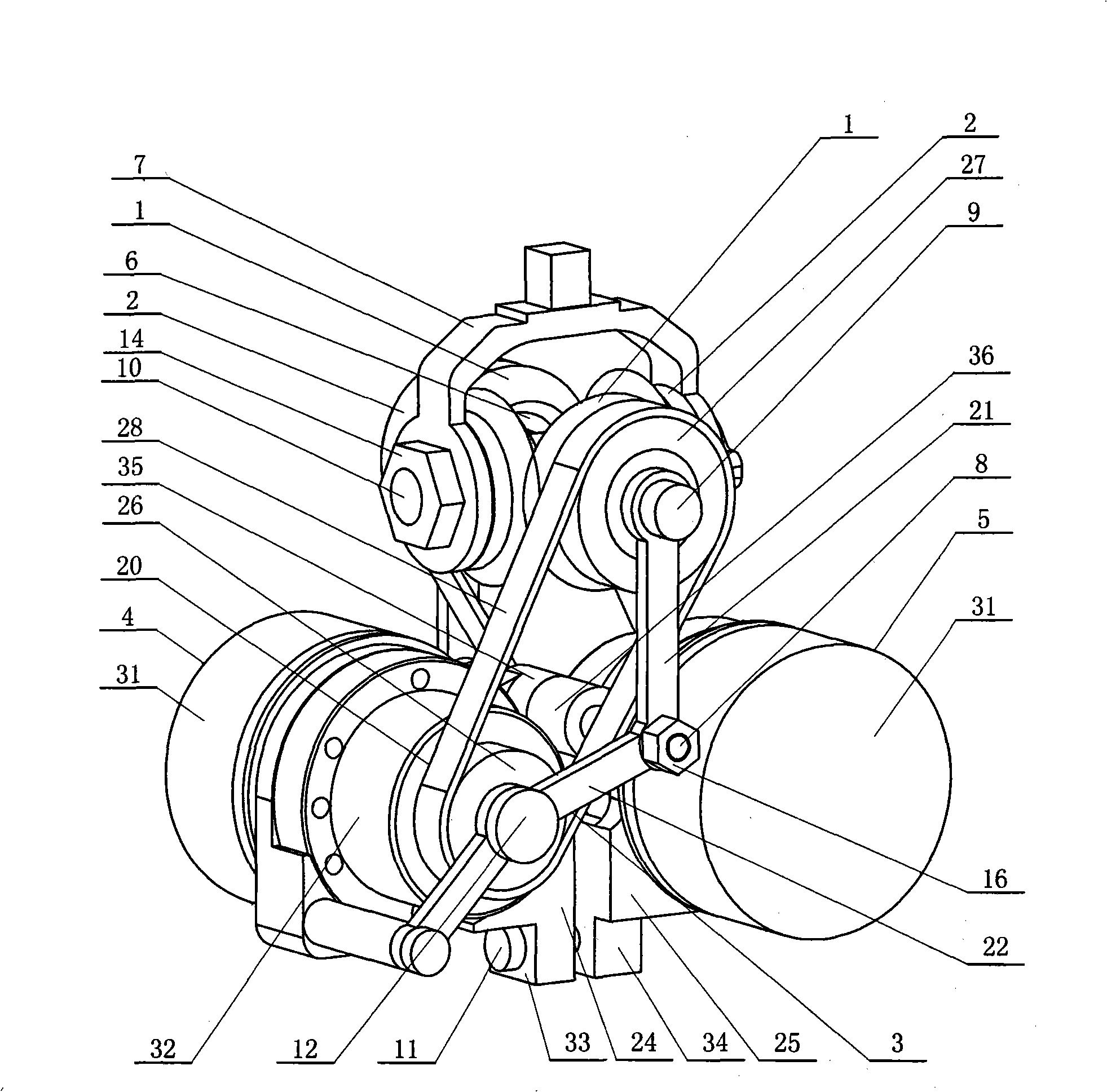
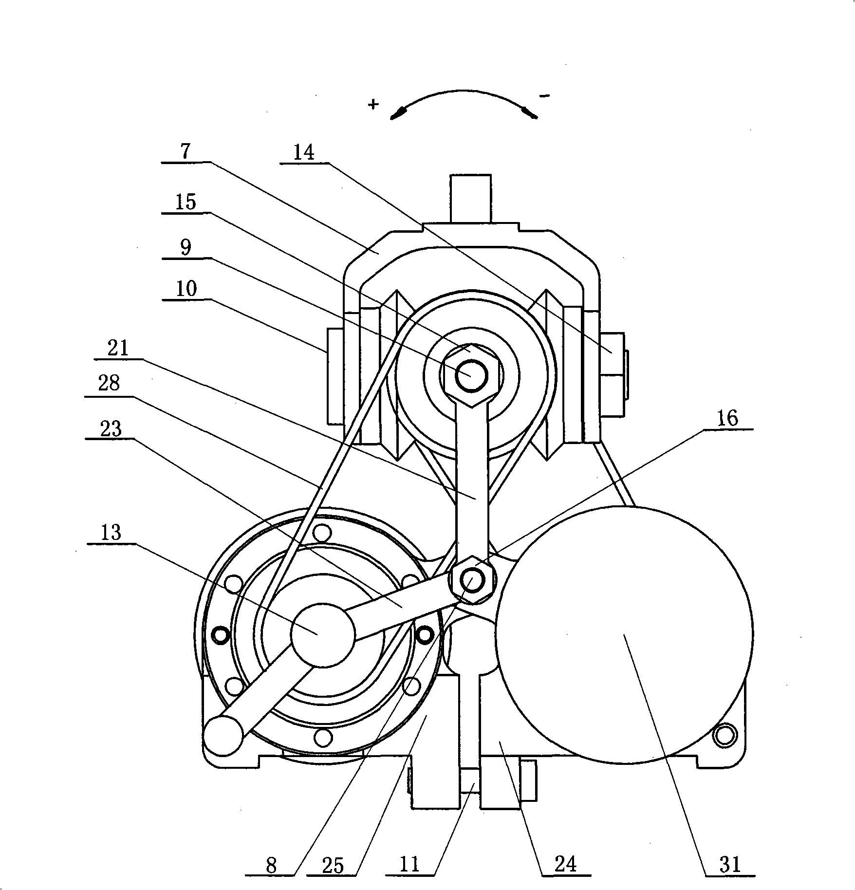
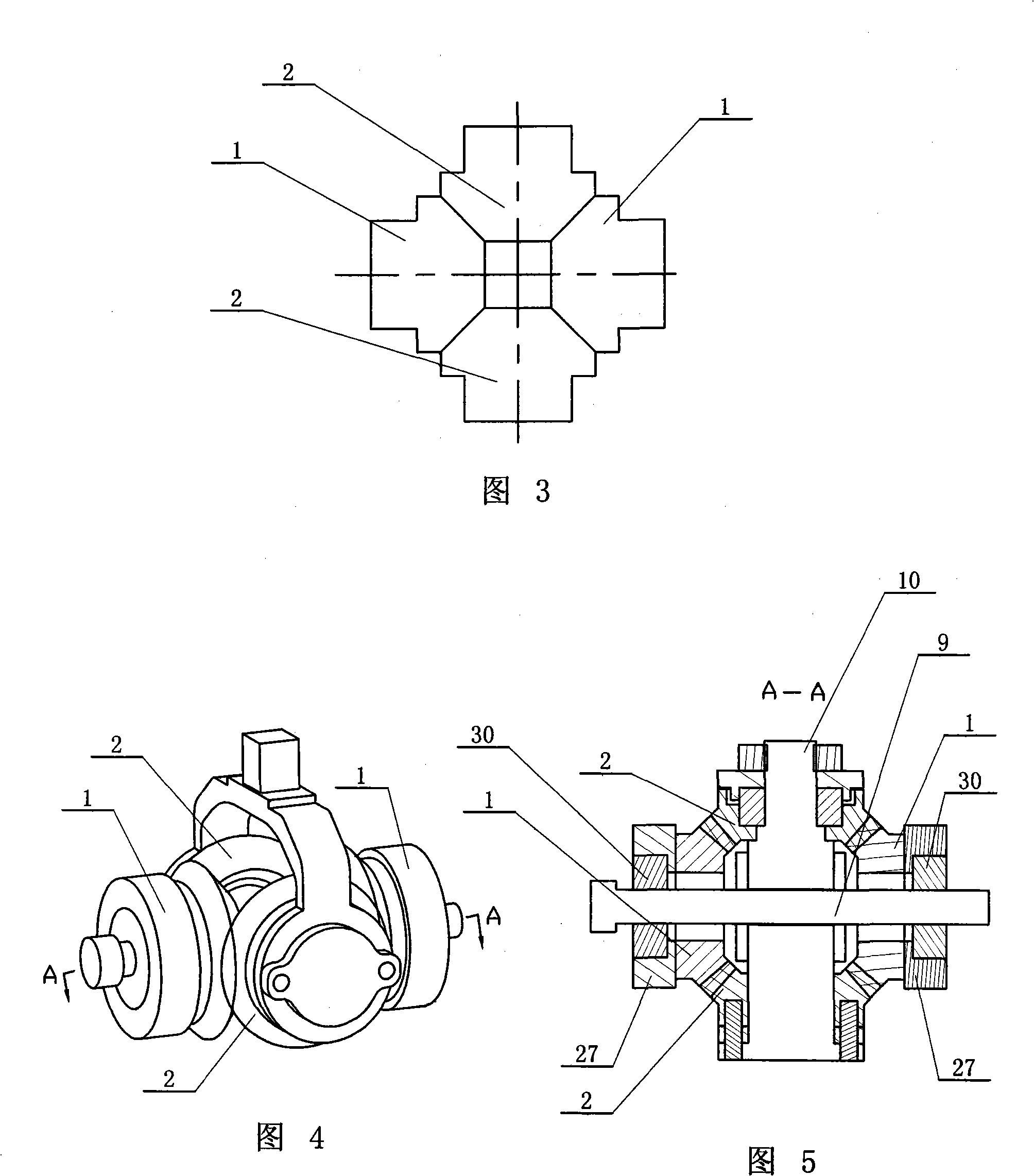
[0009] Specific implementation mode one: combine Figure 1 to Figure 10 Describe this embodiment, the finger base joint transmission mechanism of this embodiment includes a differential mechanism 6 and two driving devices; A nut 14, a second nut 15, two third nuts 16 and a connecting piece 7; the limiting mechanism in the side swing direction of the base joint is composed of the first joint shaft 9 and the second joint shaft 10, and the belt is preloaded The mechanism is composed of two belt transmission mechanisms 20, frame assembly 3, rotating shaft 8 and threaded connector 11; the differential mechanism 6 is composed of two driving bevel gears 1 and two driven bevel gears 2, and the frame assembly 3 is composed of two fixed rods 21, a first turret 22, a second turret 23, a first mount 24 and a second mount 25, and the two driving devices are respectively the first driving device 4 and the second driving device Device 5; the first mount 24 and the second mount 25 are arranged
specific Embodiment approach 2
[0011] Specific implementation mode two: combination figure 1 , figure 2 ,Figure 5, Figure 6 , Figure 8 ~ Figure 10 Describe this embodiment, each belt transmission mechanism 20 of this embodiment is made up of small pulley 26, large pulley 27, toothed belt 28, first bearing 29 and second bearing 30; On the output shaft 12 and the output shaft 13 of the second driving device 5, the first bearing 29 and the small pulley 26 are respectively equipped with, the first joint shaft 9 between the two fixed rods 21 and the two driving bevel gears 1 The second bearing 30 and the large pulley 27 are respectively installed on the top, and each of the small pulleys 26 and the large pulley 27 is connected by a toothed belt 28 transmission. In this embodiment, the differential mechanism 6, the joint shaft 9, the rotating shaft 8, the first driving shaft 12 and the second driving shaft 13 are connected through the frame assembly 3 to realize the rotation of the two driving devices around t
specific Embodiment approach 3
[0012] Specific implementation mode three: combination figure 1 and figure 2 To illustrate this embodiment, both the first driving device 4 and the second driving device 5 in this embodiment are composed of a motor 31 and a reducer 32 , and the output shaft of the motor 31 is connected to the input shaft of the reducer 32 through transmission. In this way, the motor 31 and the speed reducer 32 can be directly connected, or can be connected through gears or toothed belts. Other components and connections are the same as those in the first embodiment.
PUM
 Abstract
Description
Claims
Application Information
 - R&D Engineer
- R&D Manager
- IP Professional
- Industry Leading Data Capabilities
- Powerful AI technology
- Patent DNA Extraction
Browse by: Latest US Patents, China's latest patents, Technical Efficacy Thesaurus, Application Domain, Technology Topic.
© 2024 PatSnap. All rights reserved.Legal|Privacy policy|Modern Slavery Act Transparency Statement|Sitemap