Self-powering three-way change valve

A three-way reversing valve, self-operated technology, applied in the direction of fluid circulation arrangement, refrigeration components, refrigerators, etc., can solve the problems of short-circuit leakage of high and low pressure chambers, local resistance increase, reversing pressure difference, etc., to ensure stability performance and reliability, improve cooling efficiency, and reduce local resistance

Inactive Publication Date: 2009-05-06
ZHEJIANG CHUNHUI INTELLIGENT CONTROL
View PDF1 Cites 10 Cited by
  • Summary
  • Abstract
  • Description
  • Claims
  • Application Information

AI Technical Summary

Benefits of technology

This patented technology uses an improved design for a switch used with two different fluids: one fluid called coolant (C) while another liquid called warm water or hot water. By adding this new feature into the existing system, it ensures stable and reliable operation even when there's no extra effort needed from other components like pumps or motors. Additionally, by sharing certain parts between these fluids, they can improve their circulatory performance compared to traditional systems where only one type of fluid flows through them at once. Overall, this innovative technical solution allows better control over temperature within specific areas during air conditioning operations.

Problems solved by technology

This patented technical problem addressed in this Patents relates to improving the operation and reliance of conventional refrigrovalves used in automotive air conditioner systems due to their complexity and poor design options. These issues include difficulty achieving proper connections with other components such as sensors and actuators, insufficiently reliable control over the movement of sliding valves within the system's internal space, potential failure modes caused by excess material usage, lack of positive feedback signals at certain points along the length of each component, unstable resetting mechanisms, etc., making them challenges to operate properly without losing battery life or requiring maintenance costs.

Method used


Image

  • Self-powering three-way change valve
  • Self-powering three-way change valve
  • Self-powering three-way change valve

Examples


Embodiment Construction

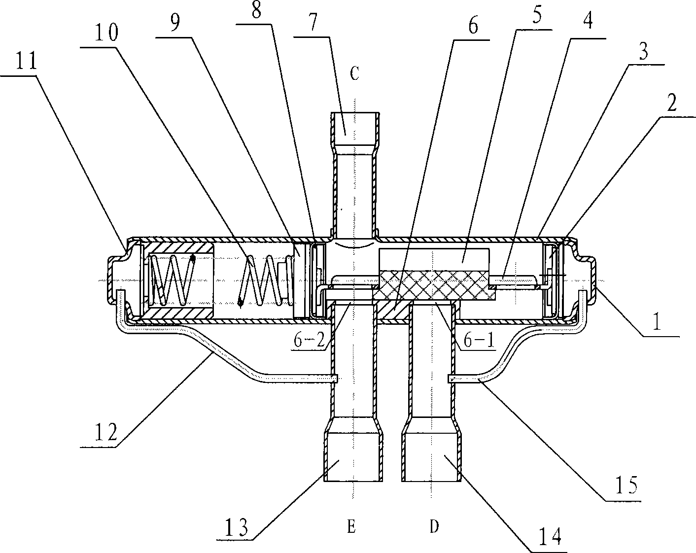
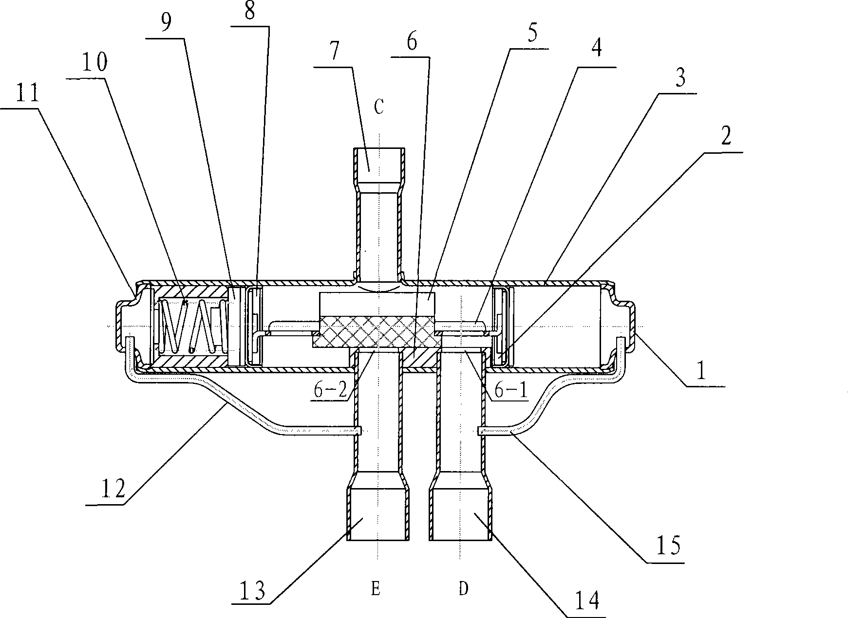
[0018] Such as figure 1 As shown, the self-operated three-way reversing valve of the present invention includes a valve body 3, the two ends of the valve body 3 have a left end cover 11 and a right end cover 1, a piston one 2, a piston two 8 in the valve body 3, a slide 4. Slider 5, and spring 10, the valve seat 6 on the valve body 3, the connecting pipe C7, the connecting pipe E13, the connecting pipe D14, the low-pressure capillary 12, and the high-pressure capillary 15 form a cavity after brazing; The block 5 is placed on the valve seat 6, the slide frame 4 is fixed with the slide block 5, and the slide frame 4 is connected with the piston one 2 and the piston two 8 to form a combination piston slide frame, which can move axially in the valve body 3 ; The spring 10 is located between the piston 2 8 and the left end cover 11, and the valve seat 6 has two valve ports. The above structure is similar to the prior art, so it will not be described in detail.

[0019] The biggest f


PUM


Abstract

The invention discloses a self-operated three-way reversal valve. The reversal valve comprises a valve body, and a first piston, a second piston, a sliding guide and a sliding block which are arranged in the valve body, and a spring. A valve seat, an adaptor tube C, an adaptor tube E and an adaptor tube D which are arranged on the valve body form a receiving cavity together with a low-pressure capillary tube and a high-pressure capillary tube. The sliding block is arranged on the valve seat. The sliding guide is fixed with the sliding block. The sliding guide is connected with the first piston and the second piston to form a piston and sliding guide assembly which can move axially in the valve body. The spring is arranged between the second piston and a left end cap. The sliding block is provided with a radially limiting structure in the valve body. The radially limiting structure is as follows: the sliding block comprises a transverse structure and a vertical structure arranged above the transverse structure; and the bottom of the transverse structure is closely attached to the valve seat; a top surface of the vertical structure of the sliding block has a longitudinal groove; and top surfaces of twp convex parts of a convex shape of the groove are closely attached an inner wall of the valve body. The structure of the valve can improve heat tube circulation refrigeration efficiency and is high in efficiency and energy-saving.

Description


Claims


Application Information

Patent Timeline
Owner ZHEJIANG CHUNHUI INTELLIGENT CONTROL
Why Eureka
Try Eureka