Electric ballast

An electronic ballast and capacitor technology, applied in electric light sources, electrical components, lighting devices, etc., can solve the problems of poor lamp energy saving effect, narrow lamp specification range, low power factor, etc., and achieve lamp energy saving. Good effect, optimized circuit design, high power factor effect

Inactive Publication Date: 2009-05-20
吕淑明 +2
View PDF0 Cites 0 Cited by
  • Summary
  • Abstract
  • Description
  • Claims
  • Application Information

AI Technical Summary

Benefits of technology

This patented electronics ballast uses advanced technology for improving its performance without sacrificing efficiency or reducing battery life time. It achieves this by optimizing certain circuits while still providing efficient light sources like LED lamps.

Problems solved by technology

The technical problem addressed in this patented text relates to improving upon existing ballasts used in fluorescence lights without sacrificing efficiency or flexibility.

Method used


Image

  • Electric ballast
  • Electric ballast

Examples


Embodiment Construction

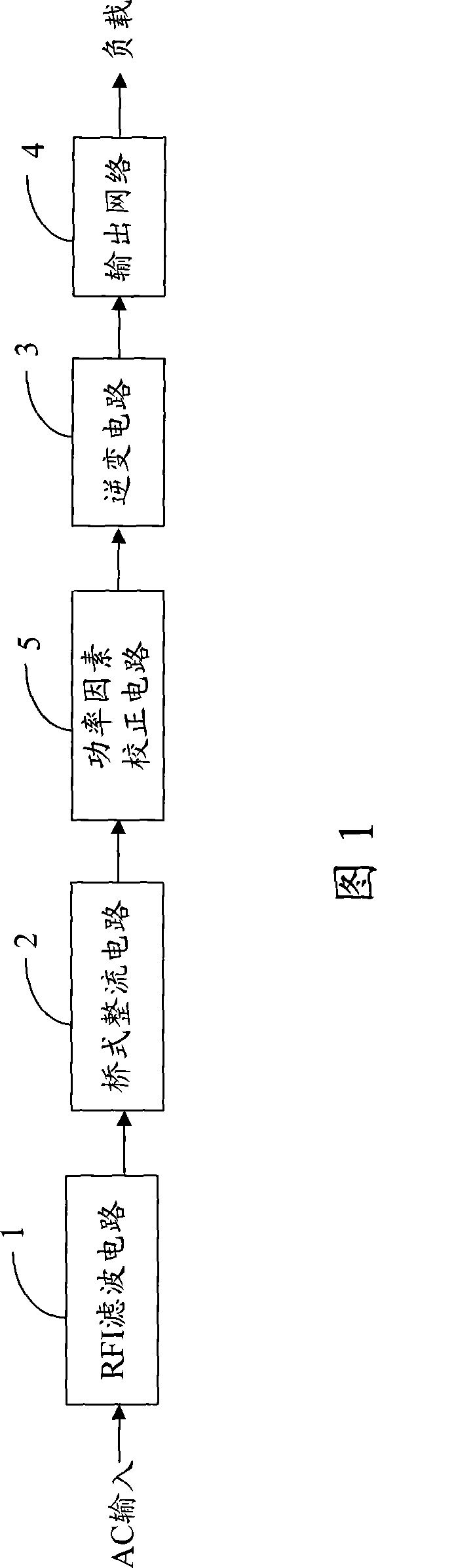
[0018] Referring to FIG. 1 , the electronic ballast provided by the present invention includes a filter circuit 1 , a rectifier circuit 2 , an inverter circuit 3 , an output network 4 and a power factor correction circuit 5 . As shown in the figure, when the electronic ballast is in use, alternating current (for example, 50 Hz commercial power) is first input to the filter circuit 1, which is filtered by the filter circuit 1; the filtered alternating current is input to the rectifier circuit 2, which is rectified The circuit 2 converts the alternating current to direct current; the direct current is then input to the power factor correction circuit 5, and the power factor correction circuit 5 obtains lower current harmonic distortion through secondary compensation, so that the power factor of the direct current voltage is increased to 0.999; after that, the inverter circuit 3. Then convert the DC voltage with improved power factor into a high-frequency AC voltage (up to 30 KHz), a


PUM


Abstract

The invention relates to an electronic ballast, which comprises a filter circuit, a rectifying circuit, an inverter circuit and an output network, wherein the filter circuit receives AC with a first frequency and filters the input AC; the rectifying circuit is used for rectifying the filtered AC so as to generate DC voltage; the inverter circuit is used for converting the DC voltage into AC voltage with a second frequency, and the second frequency is higher than the first frequency; the output network is used for connecting a load and providing the load with AC with the second frequency; and the inverter circuit is a push-pull inverter circuit and comprises a transformer, a first switching element, a second switching element, a start capacitor and a start switch. The electronic ballast has the advantages of high power factor, good energy-saving effect and wide applicable range.

Description


Claims


Application Information

Patent Timeline
Owner 吕淑明
Why Eureka
Try Eureka