Straight barrel type concrete mixing transportation truck

A technology for mixing trucks and concrete, which is applied to cement mixing devices, clay preparation devices, chemical instruments and methods, etc., can solve the problem of not overcoming energy consumption area and other problems, and achieve the effects of simple structure, reduced energy consumption, and reduced area

Inactive Publication Date: 2010-02-17
CHENGDU YUZHONGMEI SCI & TECH CO LTD
View PDF1 Cites 5 Cited by
  • Summary
  • Abstract
  • Description
  • Claims
  • Application Information

AI Technical Summary

Problems solved by technology

The weak point of this patent is: the mixing drum is still adopted to be fixed on the chassis of the car in an inclined form, so it does not overcome the large energy consumption, the large area occupi

Method used


Image

  • Straight barrel type concrete mixing transportation truck

Examples


Embodiment Construction

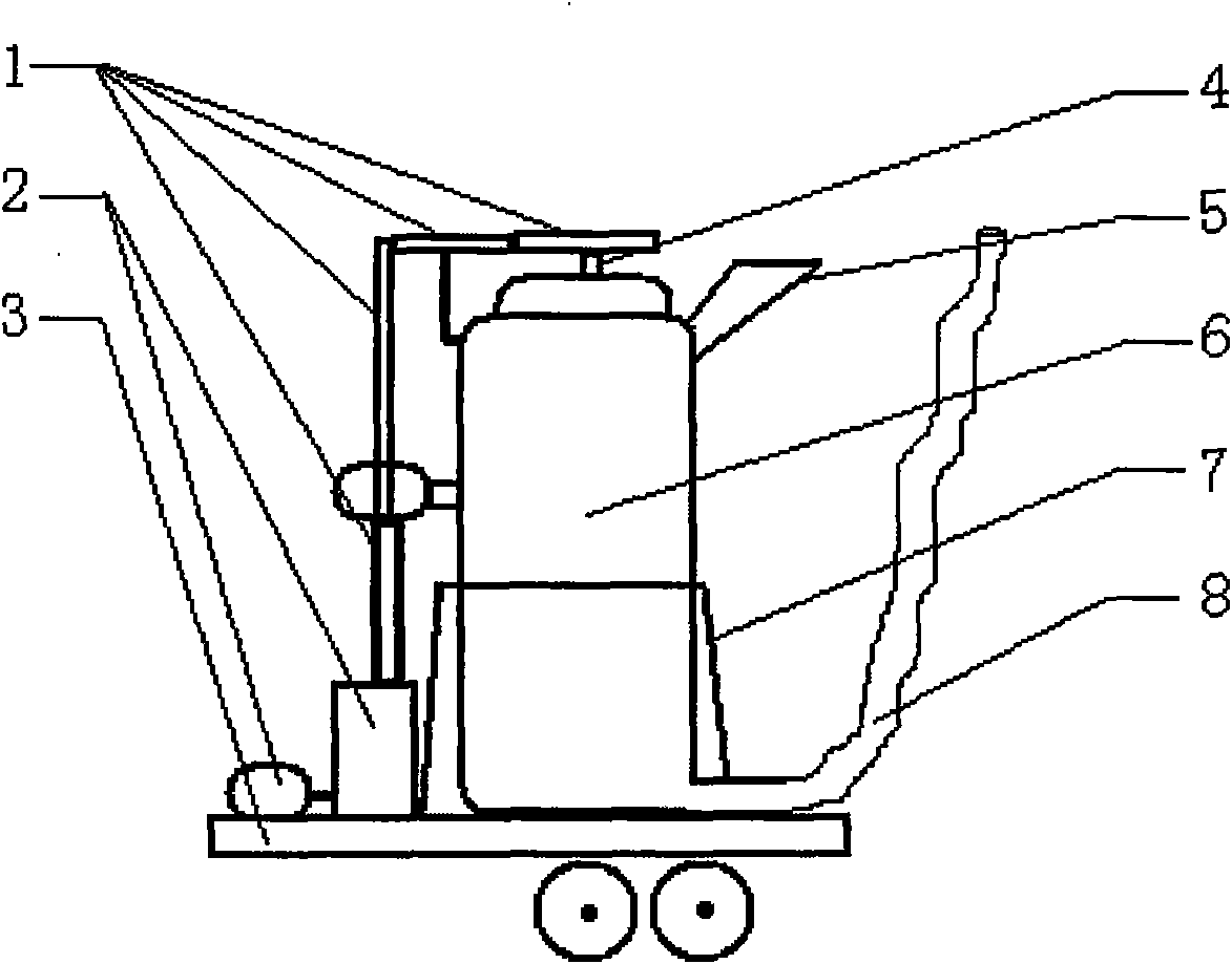
[0010] The straight bucket type concrete mixer truck provided by the present invention is composed of a straight bucket 6, a fixed frame 7, agitating blades, a transmission mechanism 1, a power mechanism 2, a material inlet 5 and a discharge pipe 8, wherein the power mechanism 2 is fixed on the vehicle On the chassis 3, there are power take-offs, reducers, hydraulic motors, hydraulic pumps, and electronic control units to provide power, which is the prior art; the straight barrel 6 is cylindrical, and the straight barrel 6 is erected and fixed on the automobile chassis 3 through the fixing frame 7 On; the stirring blade has a rotating shaft 4, and the stirring blade is inserted into the straight barrel 6 from the upper end of the straight barrel 6; the transmission mechanism 1 is fixed on the automobile chassis 3 or the wall of the straight barrel 6, connects the power mechanism 2 and the rotating shaft 4, and transmits power to Agitating blades; the feed inlet 5 is located on the


PUM


Abstract

The invention discloses a straight barrel type concrete mixing transportation truck which comprises a straight barrel, a fixing frame, a stirring blade, a transmission mechanism, a power mechanism, afeeding hole and a discharge tube. The invention has a simple structure that the stirring blade rotates but the straight barrel does not rotate so as to reduce the energy consumption; the straight barrel is vertically fixed on a vehicle chassis through the fixing frame so as to reduce the occupation area of the straight barrel on the vehicle chassis; the feeding hole is positioned on the side barrel wall of the upper part of the straight barrel and faces upwards; when the discharge tube is not used for discharging materials, the opening of the discharging tube is placed at a position higher than the feeding hole so as to avoid the condition that concrete is scattered from the feeding hole and a discharging hole when the concrete mixing transportation truck passes through a bridge and an upslope. The invention is suitable for all concrete mixing transportation trucks.

Description


Claims


Application Information

Patent Timeline
Owner CHENGDU YUZHONGMEI SCI & TECH CO LTD
Why Eureka
Try Eureka