Separate type filling method of goaf

A goaf and barrier technology, which is applied in the fields of backfill, mining equipment, earthwork drilling, etc., can solve the problems of limited control of surface subsidence, limited application and promotion, complicated filling process, etc., and achieve subsidence control. Remarkable, high filling efficiency and filling density, and simple filling method

Inactive Publication Date: 2010-05-12
JIZHONG ENERGY HANDAN MINING GROUP +1
View PDF0 Cites 34 Cited by
  • Summary
  • Abstract
  • Description
  • Claims
  • Application Information

AI Technical Summary

Benefits of technology

This patented technology allows create temporary walls inside tunnels during excavation operations by adding layers of concrete along their sides instead of just covering them completely. These reinforced structures help prevent damage from falling rocks while still allowing liquids like drilling fluid (mud) into these areas without causing any problems such as leakages. Overall, this process improves safety measures and reduces environmental concerns associated with excavations.

Problems solved by technology

The technical problem addressed by this patented method relates to improving the stability of landfill structures during coal mineralization processes when there are cracks or other defects along with damages from environmental factors such as rain erosion and flooding. Current methods for filling these areas require expensive materials like cement, sand, pigments, resin binder, and adhesive material, which can be difficult to use at an affordably price point.

Method used


Image

  • Separate type filling method of goaf
  • Separate type filling method of goaf
  • Separate type filling method of goaf

Examples


Embodiment 1

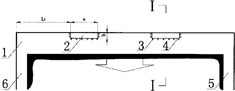
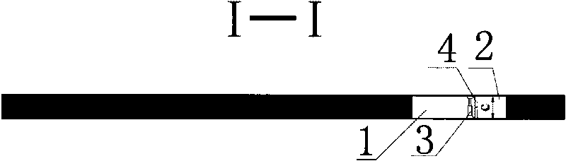
[0033] Embodiment one, Figure 1 to Figure 8 as shown,

[0034] a. In the mined-out area 1 to be filled, along the advancing direction of the coal mining face, the interval distance L is arranged longitudinally 1 Hang multiple flexible filling bags 2; the length a of the flexible filling bag 2 is about 10m to 20m, the width b is about 2m to 3m, and the height c is the same as the mining height of the working face;

[0035] b. A plurality of individual pillars 3 are arranged at intervals on the exposed side of the hanging flexible filling bag 2;

[0036] c. Erecting a template 4 on the outside of the flexible filling bag 1 and relying on the single pillar 3;

[0037] d. Fill the flexible filling bag 2 with high-water material through the filling pipe until it is full;

[0038] e. After the high-water material is solidified, the template 4 and the single pillar 3 are removed to complete a row of filling barriers;

[0039] f. With the advancement of the coal mining face, the ver

Embodiment 2

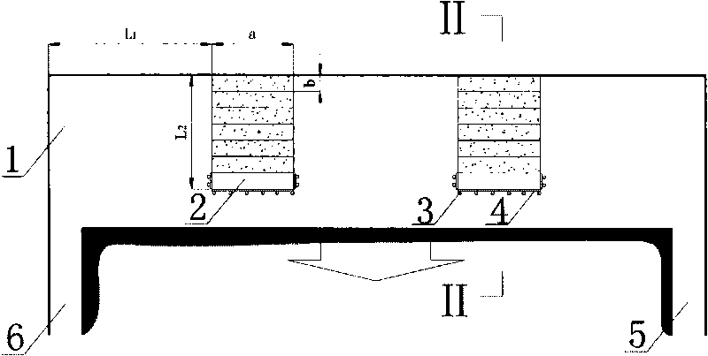
[0043] Embodiment two, Figure 9 ~ Figure 14 as shown,

[0044] a. In the mined-out area 1 to be filled, along the advancing direction of the coal mining face, the span L of the cut-off area is arranged horizontally 3 Hang multiple flexible filling bags 2; the length a of the flexible filling bag 2 is 10m-20m, the width b is 2m-3m, and the height c is the same as the mining height of the working face;

[0045] b. A plurality of individual pillars 3 are arranged at intervals on the exposed side of the hanging flexible filling bag 2;

[0046] c. Erection of the template 4 on the outside of the flexible filling bag 2 and relying on the single pillar 3;

[0047] d. Fill the flexible filling bag 2 with high-water material through the filling pipe until it is full;

[0048] e. After the high-water material is solidified, the template 4 and the single pillar 3 are removed to complete a row of filling barriers;

[0049] f. With the advancement of the coal mining face, when the advanc


PUM

PropertyMeasurementUnit
Lengthaaaaaaaaaa
Widthaaaaaaaaaa
Separation distanceaaaaaaaaaa

Abstract

The invention relates to a separate type filling method of a goaf. A plurality of flexible filling bags are hung at longitudinal or transverse intervals along the propelling direction of a coal face in the goaf and a template supported by a single brace is erected outside the filling bags. Specifically, the method includes: filling high-water materials in the filling bags; after the high-water materials are coagulated, dismantling the template and the single brace to complete a row of separation bodies; advancing along the coal face and repeating the steps until the coal advances to reach the span separating the goaf; then building a row of transverse enclosed separation body walls, irrigating the high-water materials to the enclosed wall; then continuing the work repeatedly until the coal face finishes; subsequently building an enclosed wall in a transportation alley and a track alley; and conducting final filling to complete the filling work of the whole goaf. The method uses the enclosed separation body goaf, irrigates the enclosed goaf on the basis of no accidental fall of top plates. The filling method is simple, the equipment investment is low, the filling efficiency and filling compactness are high, the stability is good and the cost is low.

Description


Claims


Application Information

Patent Timeline
Owner JIZHONG ENERGY HANDAN MINING GROUP
Why Eureka
Try Eureka