Method for producing large-power LED lamp without halo

A LED light, high-power technology, applied to optical elements, light sources, point light sources, etc. used to change the spectral characteristics of emitted light, can solve the problem of multiple light colors, difficult control of light shapes, and derivatives to application directions, etc. question

Inactive Publication Date: 2010-06-09
SHENZHEN GLORY SKY OPTOELECTRONICS CO LTD
View PDF0 Cites 2 Cited by
  • Summary
  • Abstract
  • Description
  • Claims
  • Application Information

AI Technical Summary

Problems solved by technology

At present, high-power LED lamp products on the market have yellow circles or halos around the illuminated area. The halo will reduce the lighting effect and form shadows in the illuminated area. This will cause the LED lamps with halos to be unable to illuminate Applications in areas with high color requirements
The high-power L

Method used


Image

  • Method for producing large-power LED lamp without halo
  • Method for producing large-power LED lamp without halo
  • Method for producing large-power LED lamp without halo

Examples


Embodiment Construction

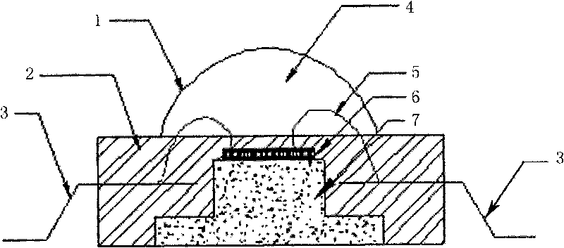
[0019] The following will combine Figure 1 to Figure 6 The present invention is further described: a method for manufacturing a halo-free high-power LED lamp, which is mainly realized by the following methods:

[0020] The first step: solid crystal.

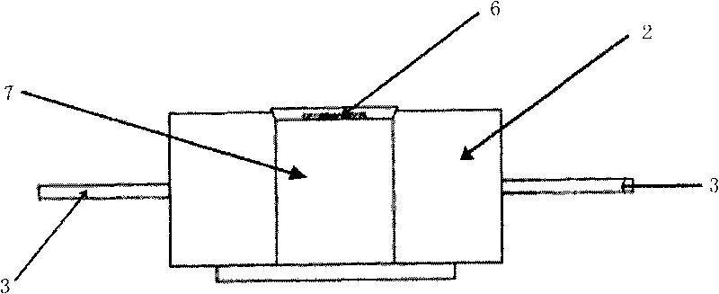
[0021] In this step see image 3 The chip 6 is bonded and fixed on the copper column 7 installed on the support 2 by silver glue, and the support 2 is formed by PPA plastic material, and the copper column 7 can help the chip 6 to dissipate heat.

[0022] Step Two: Soldering the Wires.

[0023] In this step see Figure 4 That is, the four electrodes on the chip 6 are connected to the two positive and negative electrodes provided on the positive and negative pins 3, so that the LED lamp forms an electrical circuit.

[0024] The third step: point fluorescent powder.

[0025] In this step see Figure 5 , that is, smear the fluorescent glue 8 composed of phosphor powder and colloidal silicon on the wafer 6, so that the fluorescent


PUM


Abstract

The invention provides a method for producing a large-power LED lamp without a halo, which comprises the steps of: firstly, fixing a wafer, i.e. the wafer is fixed on a copper column which is arranged on a bracket by splicing with elargol; secondly, welding a wire, i.e. the anode and the cathode of the wafer are connected with two welding pans of a pin, so that the LED is formed into an electric loop; thirdly, pointing fluorescent powder, i.e. the wafer is coated with fluorescent gel which consists of the fluorescent powder and the colloidal silica, so that the fluorescent gel is covered on all wafer to achieve a good light emission effect; and fourthly, sealing outer sealing gel, i.e. a transparent outer sealed lens is internally injected with the sealing gel, the sealing gel is further added with a chemical industrial dispersing agent, and the other impure lights and colors are removed by the chemical industrial dispersing agent.

Description


Claims


Application Information

Patent Timeline
Owner SHENZHEN GLORY SKY OPTOELECTRONICS CO LTD
Why Eureka
Try Eureka