Electronic grip tester

A tester and electronic technology, applied in sports accessories, muscle training equipment, gymnastics equipment, etc., can solve the problems of unable to record grip curve comparison in real time, and the range of grip strength cannot be adjusted, etc., to achieve convenient reference, convenient grip strength test, and a broad market foreground effect

Inactive Publication Date: 2010-07-28
NORTH CHINA UNIVERSITY OF SCIENCE AND TECHNOLOGY
View PDF0 Cites 4 Cited by
  • Summary
  • Abstract
  • Description
  • Claims
  • Application Information

AI Technical Summary

Problems solved by technology

[0003] The purpose of the present invention is to solve the shortcomings of the traditional electronic grip strength tester that the range of grip strength cannot be adjusted, and the grip strength curve cannot be recorded in r

Method used


Image

  • Electronic grip tester
  • Electronic grip tester
  • Electronic grip tester

Examples


Example Embodiment

[0022] The present invention will be described in detail below with reference to the drawings and implementation.

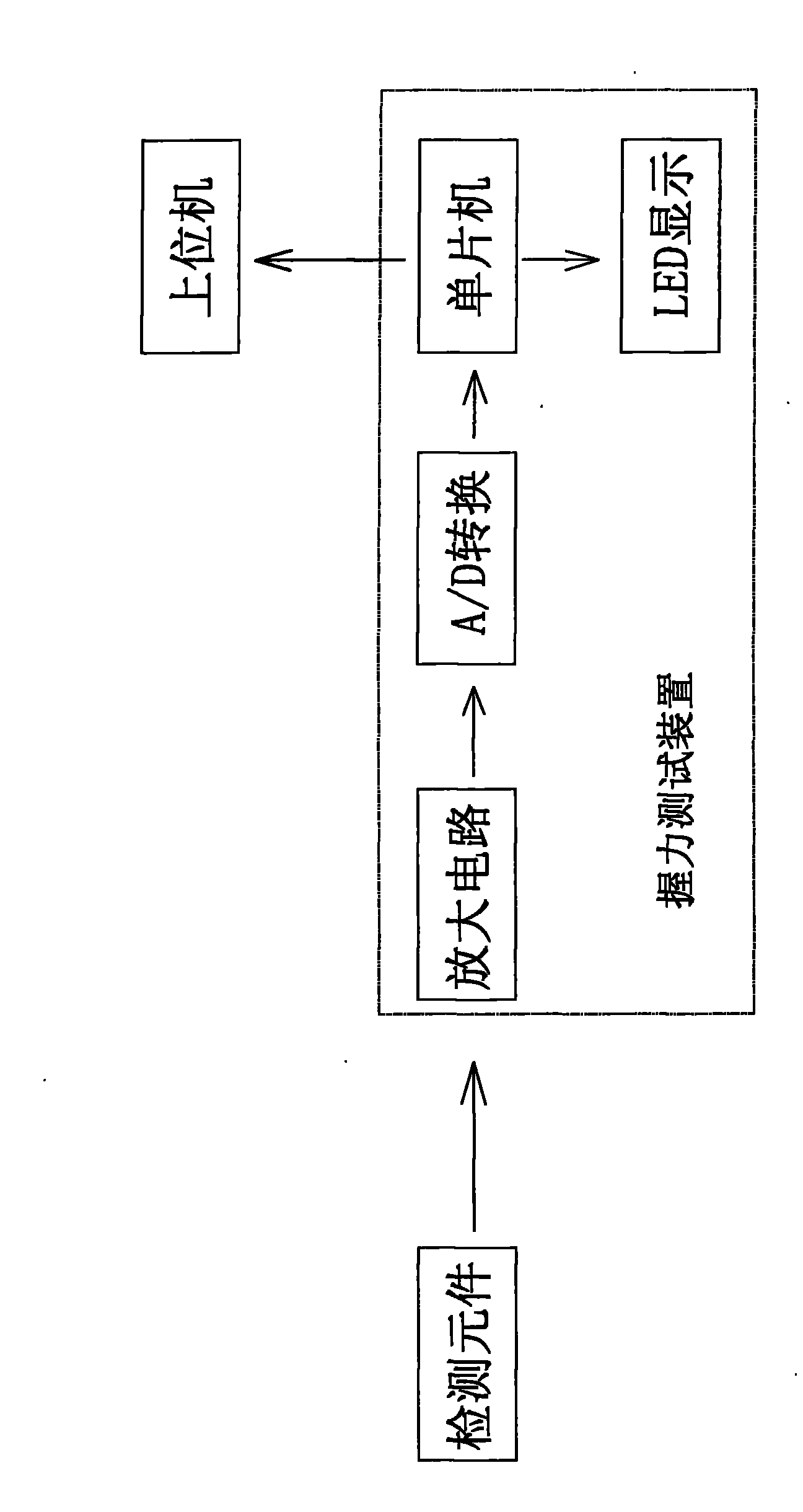
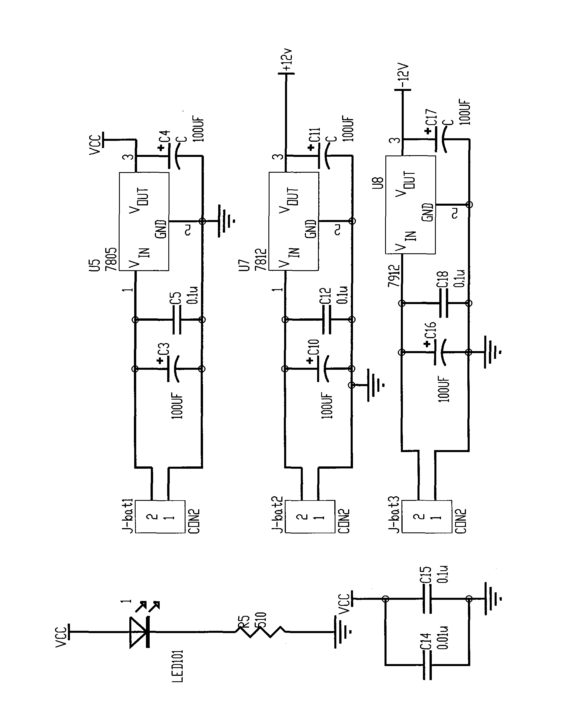
[0023] See attached Figure 1-8 In this embodiment, this electronic grip strength tester includes a grip strength handle provided with a sensor and a grip strength test device. The grip strength handle and the grip strength test device are connected by wires. The grip strength test device is equipped with a single-chip microcomputer, and the grip strength test device Connect to the external host computer;

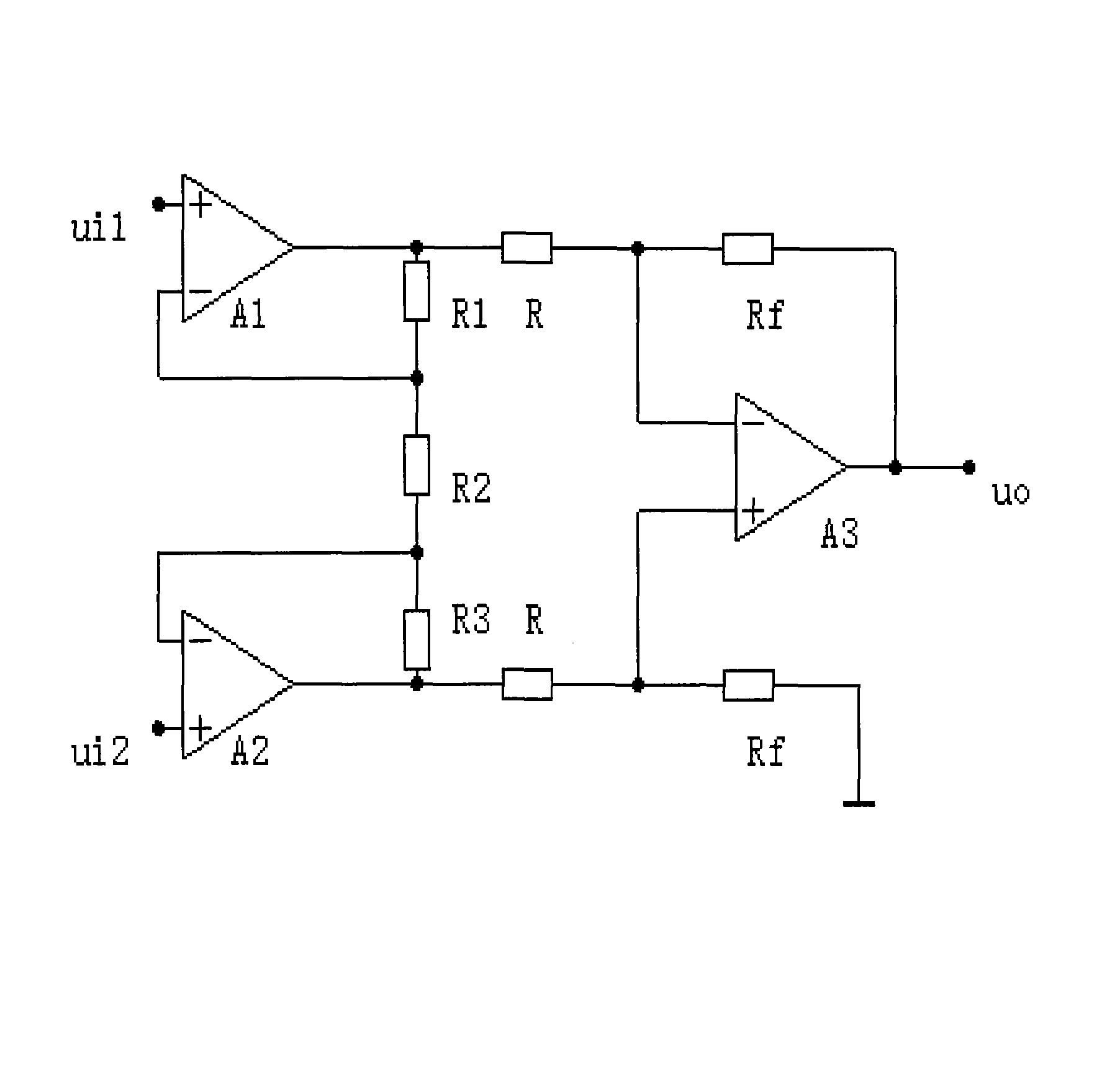
[0024] The input interface of the grip strength test device includes a pressure sensor, a data acquisition amplifier circuit and an A / D conversion circuit;

[0025] The output interface of the grip strength test device includes a digital tube display circuit and a serial interface circuit;

[0026] The grip strength test device is connected with the input terminal of the upper computer through a serial interface circuit.

[0027] The grip strength tester given in this


PUM


Abstract

The invention relates to an electronic grip tester capable of monitoring in real time, comprising a grip handle and a grip testing device, wherein the grip handle is provided with a sensor; a single chip microcomputer is arranged in the grip testing device, and the grip testing device is connected with an upper computer outside the grip testing device; the input interface of the grip testing device comprises a pressure sensor, a data acquisition amplifying circuit and an A/D conversion circuit; the output interface of the grip testing device comprises a digital tube display circuit and a serial interface circuit; and the grip testing device is connected with the input end of the upper computer through the serial interface circuit. Compared with the traditional mechanical grip tester and the traditional electronic grip tester, the electronic grip tester of the invention can be used for displaying a real-time grip curve, printing test results and better observing the recovery conditions of patients with myasthenia and the like, provides a basis for treatment of doctors, can save patient information which is convenient for searching, and has wide market potential.

Description


Claims


Application Information

Patent Timeline
Owner NORTH CHINA UNIVERSITY OF SCIENCE AND TECHNOLOGY
Why Eureka
Try Eureka