High- and low -voltage input balancing power factor correction circuit

A power factor correction, high and low voltage technology, applied in the field of high and low voltage input balanced power factor correction circuits, can solve the problem that the PFC control circuit module cannot correct power factor balance, and achieves improved loop bandwidth, low implementation cost, and simple circuit structure. Effect

Inactive Publication Date: 2011-01-26
MOSO POWER SUPPLY TECH
View PDF4 Cites 2 Cited by
  • Summary
  • Abstract
  • Description
  • Claims
  • Application Information

AI Technical Summary

Benefits of technology

This new technology simplifies its construction while reducing costs compared to previous designs without any extra components like resistors. It uses two different circuits together instead of just one for each other's purpose. By doing this, there will be more stable power supply even at higher voltages than previously possible due to increased current flowing through them.

Problems solved by technology

This patented technical problem addressed in this patents relates to improving the accuracy of adjusting the power supplied for electronic devices such as computers when supplying alternating current (AC) signals from different sources over varying voltages without affecting their performance characteristics.

Method used


Image

  • High- and low -voltage input balancing power factor correction circuit
  • High- and low -voltage input balancing power factor correction circuit
  • High- and low -voltage input balancing power factor correction circuit

Examples


Embodiment Construction

[0012] This embodiment is a preferred implementation mode of the present invention, and other principles and basic structures that are the same or similar to this embodiment are within the protection scope of the present invention.

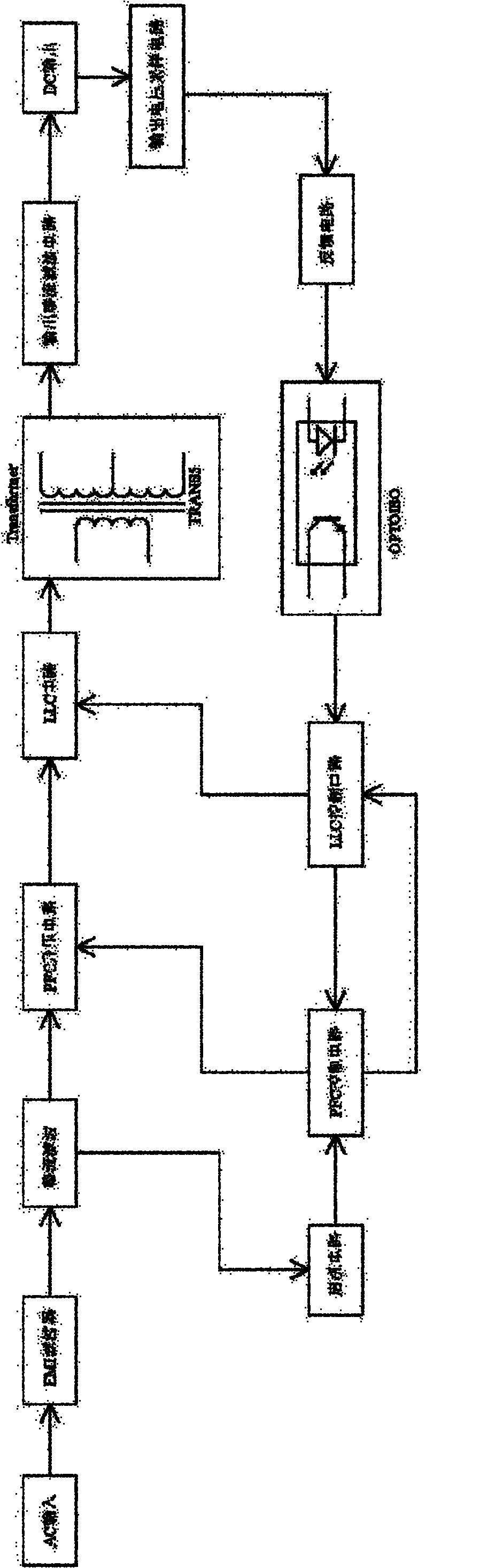
[0013] Please see attached figure 1 , the switching power supply circuit used in the present invention has the same structure as the switching power supply circuit in the prior art. It is all input AC mains power through an AC input module, and then after the rectification and filtering of the EMI filter module and the pre-stage rectification filter module, it becomes into direct current, and then divided into two paths, one of which is the power branch, and the other is the control branch. The power supply branch is input to the transformer after passing through the PFC step-up circuit module and the LLC circuit module. After the output of the transformer is rectified and filtered by the post-stage rectification and filter circuit module, it outputs


PUM


Abstract

The invention discloses a high- and low -voltage input balancing power factor correction circuit, which comprises a power factor correction (PFC) chip, wherein a feedback pin of the PFC chip is connected with a compensation circuit which comprises a remote control (RC) circuit formed by connecting a resistor R41 and a capacitor C21 in series, and a capacitor C10 connected with the RC circuit in parallel. The circuit of the invention has a simple structure, basically needs no extra circuit elements and is low in realization cost. In the invention, the traditional design bias is overcome, the resistor in the compensation circuit is replaced by the capacitor, and the RC circuit is used in combination to form a dual-electrode circuit; and thus, a loop bandwidth is greatly improved, a relatively high PF value can be kept at high-voltage input and low-voltage input, and the fluctuation range of voltage is expanded to 90 to 305V.

Description


Claims


Application Information

Patent Timeline
Owner MOSO POWER SUPPLY TECH
Why Eureka
Try Eureka