Seat slide apparatus for vehicle

A technology of deceleration device and electric seat, which is applied in the direction of electromechanical device, movable seat, transmission device, etc., can solve problems such as increase in manufacturing cost, and achieve the effect of reducing overall weight and cost

Active Publication Date: 2011-03-23
AISIN SEIKI KK
View PDF5 Cites 9 Cited by
  • Summary
  • Abstract
  • Description
  • Claims
  • Application Information

AI Technical Summary

Benefits of technology

The technical effect of this patented technology reduces the size or complexity of the reducer while maintaining its performance level for use with different types of equipment such as vehicles.

Problems solved by technology

This patented technical problem addressed in this patents relates to improving the efficiency or performance of power seats used in vehicles while minimizing their complexity and assembly time.

Method used


Image

  • Seat slide apparatus for vehicle
  • Seat slide apparatus for vehicle
  • Seat slide apparatus for vehicle

Examples


Embodiment Construction

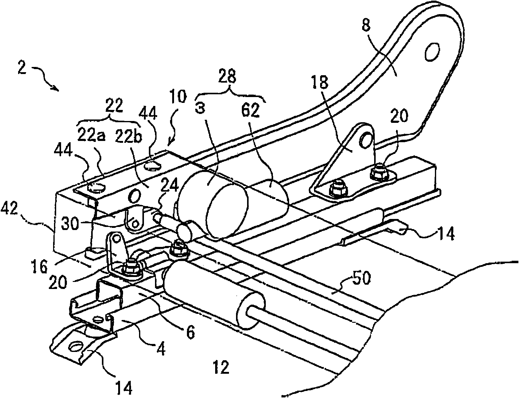
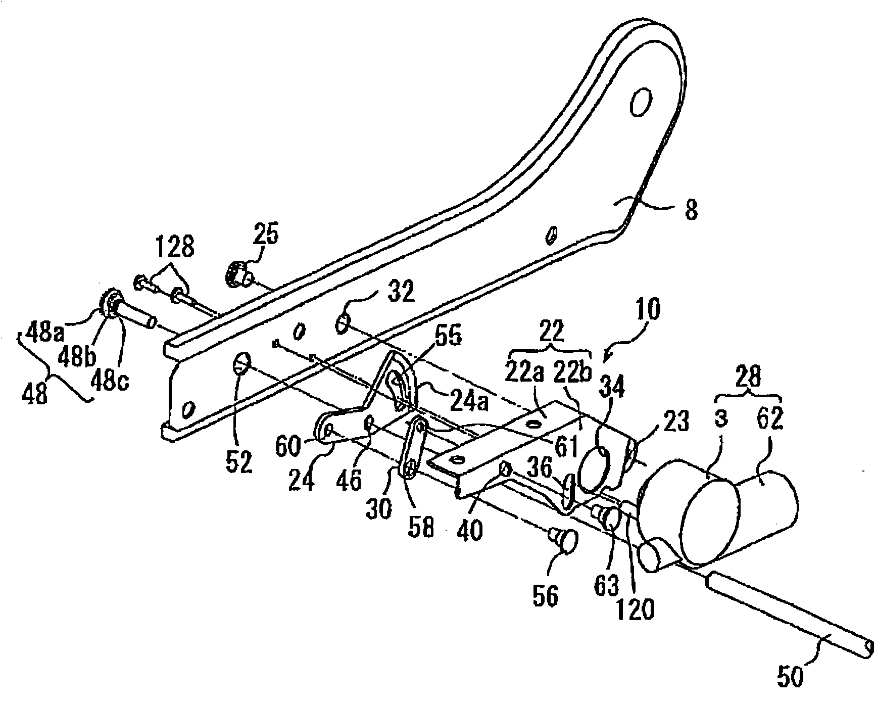
[0026] Next, the reduction gear device according to the first embodiment applied to the seat reclining apparatus for the vehicle seat apparatus will be described. Hereinafter, directions and orientations such as front-rear (ie, longitudinal direction), left-right (width direction), and top-bottom correspond to observations by a passenger seated on a vehicle seat (ie, a power seat) direction and orientation. Further, hereinafter, the seat reclining apparatus provided at the right side of the seat will be mainly explained as an example.

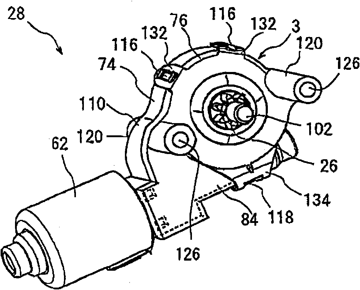
[0027] like figure 1 As shown, the seat apparatus 2 for a vehicle includes a lower rail 4 , an upper rail 6 , a lower arm 8 serving as a seat frame and on which a seat cushion is mounted, and a seat reclining apparatus 10 . The seat reclining apparatus 10 includes a drive motor unit 28 including the reduction gear 3 . According to the seat arrangement 2 , the lower rail 4 extending in the longitudinal direction of the vehicle is fixed to the fl


PUM


Abstract

A speed reduction device (3) for a power seat (2) includes a worm gear (72), a helical gear (82), a casing including a casing body (74, 135) and a casing cover (76), and a motor fixation device (87). The motor fixation device (87) includes a first fitting portion (64, 141, 137, 138) provided at a housing (68, 136), a first engagement portion (64a, 136b) formed at the first fitting portion (64, 141), a second fitting portion (74a, 135a, 110) formed at the casing body (74, 135) and to which the first fitting portion (64, 138) is fitted, a second engagement portion (74b, 135b) formed at the second fitting portion (74a, 110) and arranged to overlap the first engagement portion (64a, 136b) in a direction perpendicular to the output shaft (62a) of the motor (62) in a case where the first fitting portion (64, 138) is fitted to the second fitting portion (74a, 135a), and an engagement projection (76a) formed at the casing cover (76) and engaging with the first engagement portion (64a, 136b) and the second engagement portion (74b, 135b) in a case where the casing cover (76) is tightened to the casing body (74, 135).

Description


Claims


Application Information

Patent Timeline
Owner AISIN SEIKI KK
Why Eureka
Try Eureka