Vertical centrifugal pump impeller positioning device

A centrifugal pump impeller and positioning device technology, which is applied to non-variable pumps, parts of pumping devices for elastic fluids, pumps, etc., can solve the problems of high processing accuracy, high manufacturing cost, and easy falling of impellers , to achieve the effect of low machining accuracy, low manufacturing cost and easy processing

Inactive Publication Date: 2011-05-04
SHUANGLUN GRP CO LTD SHANDONG
View PDF0 Cites 0 Cited by
  • Summary
  • Abstract
  • Description
  • Claims
  • Application Information

AI Technical Summary

Problems solved by technology

[0003] The technical problem solved by the present invention is to solve the problems of high processing accuracy, difficult processing, high manufacturing cost, and impeller is easy to fall off, which affects norma

Method used


Image

  • Vertical centrifugal pump impeller positioning device
  • Vertical centrifugal pump impeller positioning device

Examples


Embodiment Construction

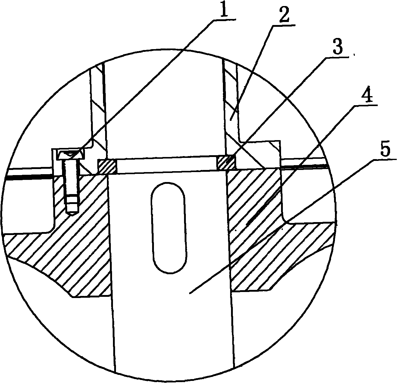
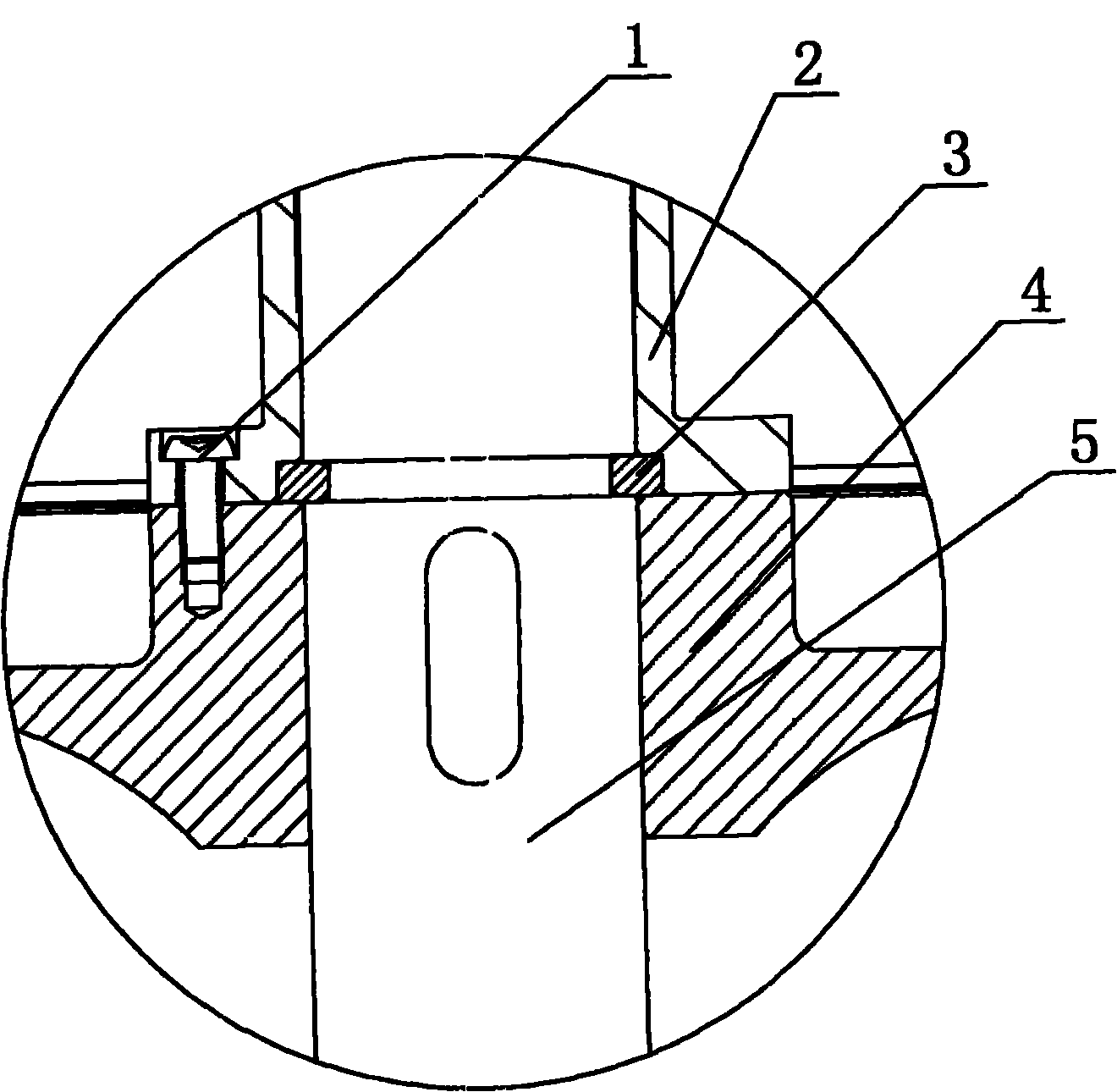
[0007] As shown in the vertical centrifugal pump impeller positioning device, the pump shaft 5 is provided with an impeller 4, and the pump shaft 5 on one side of the impeller 4 is provided with a ring groove, and a snap ring 3 is provided in the ring groove, and the snap ring 3 is on the other side. There is a shaft sleeve 2 on the side, and a screw 1 is provided on the shaft sleeve 2. The screw 1 fastens the shaft sleeve 2 and the impeller 4 and is stuck on the snap ring 3. Since the pump shaft 5 on the side of the impeller 4 is provided with a ring groove, A snap ring 3 is provided in the ring groove, and a shaft sleeve 2 is provided on the other side of the snap ring 3, and a screw 1 is provided on the shaft sleeve 2, and the screw 1 fastens the shaft sleeve 2 and the impeller 4 and is stuck on the snap ring 3, each The machining accuracy requirements of these parts are low, the machining is easy, the manufacturing cost is low, the impeller is not easy to fall off, and the nor


PUM


Abstract

The invention relates to a vertical centrifugal pump impeller positioning device which relates to a centrifugal pump impeller positioning device. A pump shaft is provided with an impeller, an annular groove is arranged on the pump shaft at one side of the impeller and internally provided with a snap ring, the other side of the snap ring is provided with a shaft sleeve, a screw is arranged on the shaft sleeve, tightly fixes the shaft sleeve and the impeller together and clamps the shaft sleeve and the impeller on the snap ring. Because the annular groove is arranged on the pump shaft at one side of the impeller and internally provided with the snap ring, the other side of the snap ring is provided with the shaft sleeve, the screw is arranged on the shaft sleeve, tightly fixes the shaft sleeve and the impeller together and clamps the shaft sleeve and the impeller on the snap ring, all parts require low processing accuracy, are easy to process and have low manufacture cost, the impeller is not easy to drop and the normal use is not influenced, the vertical centrifugal pump impeller positioning device is suitable for positioning vertical centrifugal pump impellers.

Description


Claims


Application Information

Patent Timeline
Owner SHUANGLUN GRP CO LTD SHANDONG
Why Eureka
Try Eureka