Solid-state fluidization mining jet flow recovery flow field detection experiment device and experiment method
A technology of solid-state fluidized mining and experimental equipment, which is applied in the direction of measuring equipment, fluid dynamics test, machine/structural component testing, etc., and can solve problems such as unclear mechanism of action
- Summary
- Abstract
- Description
- Claims
- Application Information
AI Technical Summary
Problems solved by technology
Method used
Image

Examples
Embodiment
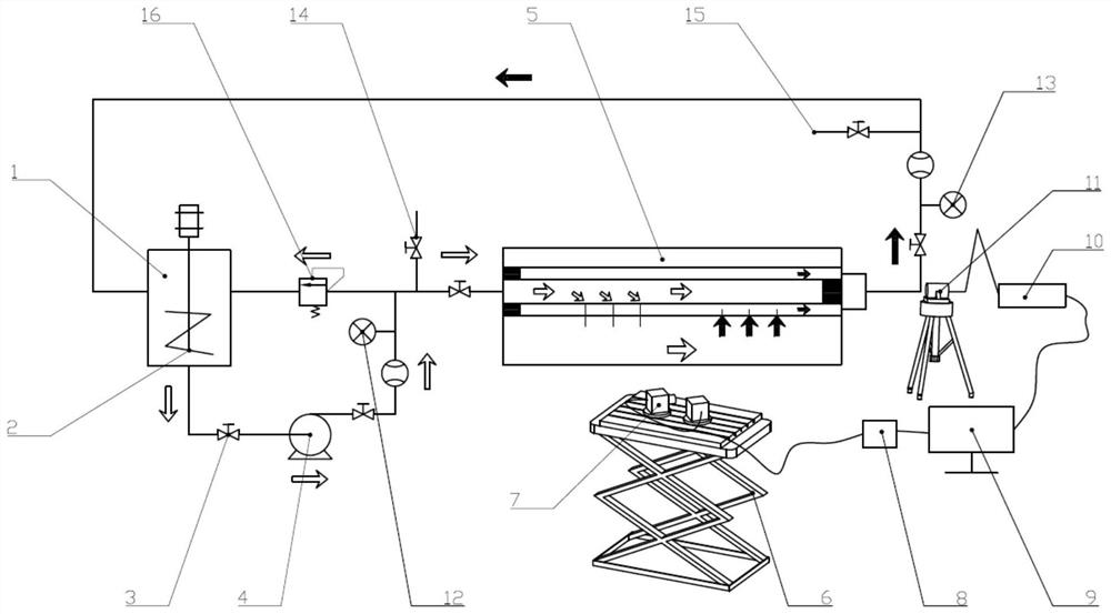
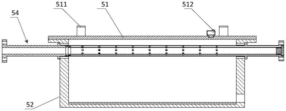
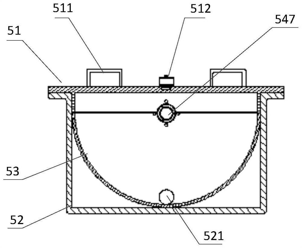
[0037] like Figure 1 to Figure 8 As shown, an experimental device for detecting the flow field of jet recovery in solid-state fluidized mining includes a slurry prefabrication module, a centrifugal pump 4 whose liquid inlet is connected to the liquid outlet of the slurry prefabrication module through a pipeline, and the liquid inlet is connected to the centrifugal pump through a pipeline. 4 The jet recovery module 5, which is connected to the liquid outlet and is transparent as a whole, communicates with the jet recovery module 5 and the slurry prefabrication module through pipelines and is used for pressure relief. The overflow valve 16 is connected to the fluid inlet and outlet of the jet recovery module 5 through pipelines The liquid port is connected to the front sampling port 14 and the rear sampling port 15 for sampling, and the flow field detection and display module for detecting the liquid from the jet recovery module 5; the slurry prefabrication module includes a liquid
Embodiment 1
[0040] Single nozzle submerged jet experiment
[0041]Correctly connect the pipeline (only enable a single nozzle (d=4.0mm) to be placed on the symmetrical surface of the semicircular cavity, and arrange the recovery port remotely) and the link of the flow field detection and display module, and fill the crushing cavity with water;
[0042] Turn on the pump to circulate clean water between the overflow valve and the liquid storage tank, check for liquid leakage, adjust the pressure to 3MPa, close the valve to the liquid storage tank after stabilization, and open the valve to the jet recovery module;
[0043] After the pressure is stabilized, the image of the single nozzle jet flow field is taken, and the nozzle divergence angle, flow velocity data and streamline data are obtained through processing and analysis;
[0044] Change the pressure value to 5MPa, 7MPa, 9MPa and repeat the above steps,
[0045] Maintain the pressure at a specific value, change the size of the nozzle (d=2
Embodiment example 2
[0048] The structure and working principle of this embodiment are basically the same as that of Embodiment 1, the difference is that two nozzles are arranged in the circumferential direction or radial direction, and by changing the angle between the two nozzles in the circumferential direction or the distance between the two nozzles in the radial direction, the circumferential or radial Flow field data for an axial section. Find the influence law of the included angle and spacing on the flow field. Specific steps are as follows
[0049] Two jet nozzles of the same size are arranged in the same circle on the double-layer pipe,
[0050] Take the flow field image of the section where the nozzles are arranged, and obtain the velocity, energy distribution and streamline diagram of the flow field under the coupling action of the two nozzles;
[0051] Change the angle between the two nozzles, repeat the above experimental steps;
[0052] Arrange two nozzles along the same axis of the
PUM
 Abstract
Description
Claims
Application Information
 - R&D Engineer
- R&D Manager
- IP Professional
- Industry Leading Data Capabilities
- Powerful AI technology
- Patent DNA Extraction
Browse by: Latest US Patents, China's latest patents, Technical Efficacy Thesaurus, Application Domain, Technology Topic.
© 2024 PatSnap. All rights reserved.Legal|Privacy policy|Modern Slavery Act Transparency Statement|Sitemap